Modular Instrumentation for Analyzing Biological Fluids

a biological fluid and module technology, applied in the field of analytical systems, can solve the problems of many physician office laboratories closing, many physician office laboratories being closed, etc., to achieve convenient service and/or upgrade, and efficient and distributed diagnostic infrastructure

Active Publication Date: 2016-10-20
THE GENERAL HOSPITAL CORP
View PDF3 Cites 8 Cited by
  • Summary
  • Abstract
  • Description
  • Claims
  • Application Information

AI Technical Summary

Benefits of technology

[0010]The present disclosure relates to improved systems and methods for diagnostics testing. The new systems enable sophisticated and complex testing equipment to be implemented at the point of care and enable an efficient and distributed diagnostics infrastructure. By designing the analytic system to have modular components, which may be of a plug-and-play type, systems can be built that are both flexible in the types of diagnostic tests that they can perform and that are easily serviceable and / or upgradeable by the replacement of one or more of the modules. Replacement modules can be shipped or couriered to the point of care and modules that need to be repaired or serviced can be sent to a skilled technician who resides off-site. In some embodiments, one or more of the modules may be non-serviceable or disposable.

Problems solved by technology

At least in part, this trend was due to perceived problems in quality control stemming from performing testing at various points of care with traditional diagnostic technology.
For example, in comparison to a large medical center with a sizable staff of highly skilled technicians, a small town physician's office with a small independent lab was believed to lack the oversight and technical support necessary to properly operate and service complicated laboratory equipment.
From 1988 forward, many physician office laboratories were closed, as they were unable to comply with the requirements of the CLIA.
While this centralized approach may have been a solution for controlling the quality of diagnostic information considering the technology at the time, it is not without its problems.
Perhaps the greatest problem is that patients in medically underserved areas, which are primarily served by physicians operating out of small or mobile offices, now had reduced access to important diagnostic testing.
Test samples either needed to be collected and transported (which can present potential additional cost and handling) or patients needed to travel to a centralized laboratory facility to have tests performed (which may require that patients living in rural environments travel a great distance, which can dissuade some patients from having the test performed at all due to the cost or the time associated with travel).
However, their limited adoption reveals the many challenges of moving testing to the point of care in the current healthcare environment.
Among the problems are that most current point of care solutions either significantly sacrifice quality to try to compete with centralized laboratory services on cost (for example, most lab-on-a-chip designs have a target price point that requires significant tradeoffs between cost and performance) or are not particularly economical as a whole (for example, multiple systems are required for various types of analytes and many physicians must still rely a centralized laboratory to meet at least some of their routine testing needs).
At a small or medium sized testing facility, it can be hard to justify the expense of separate systems for different types of tests where testing volume is relatively low.
Further, selecting a suite of efficient devices is often difficult as there is often redundant, unshared hardware across the various devices yet, due to differences in the device interfaces, middleware must still be obtained to integrate and connect the various devices into a single laboratory information system.
At the same time, having multiple testing devices takes up significant laboratory real estate and can mean separate systems to operate and maintain, separate contracts to manage, and separate manufacturers and vendors.
Thus, even with the high desirability of a return to point of care diagnostics testing, currently there has been very limited adoption of this model.

Method used


Image

  • Modular Instrumentation for Analyzing Biological Fluids
  • Modular Instrumentation for Analyzing Biological Fluids
  • Modular Instrumentation for Analyzing Biological Fluids

Examples


Embodiment Construction

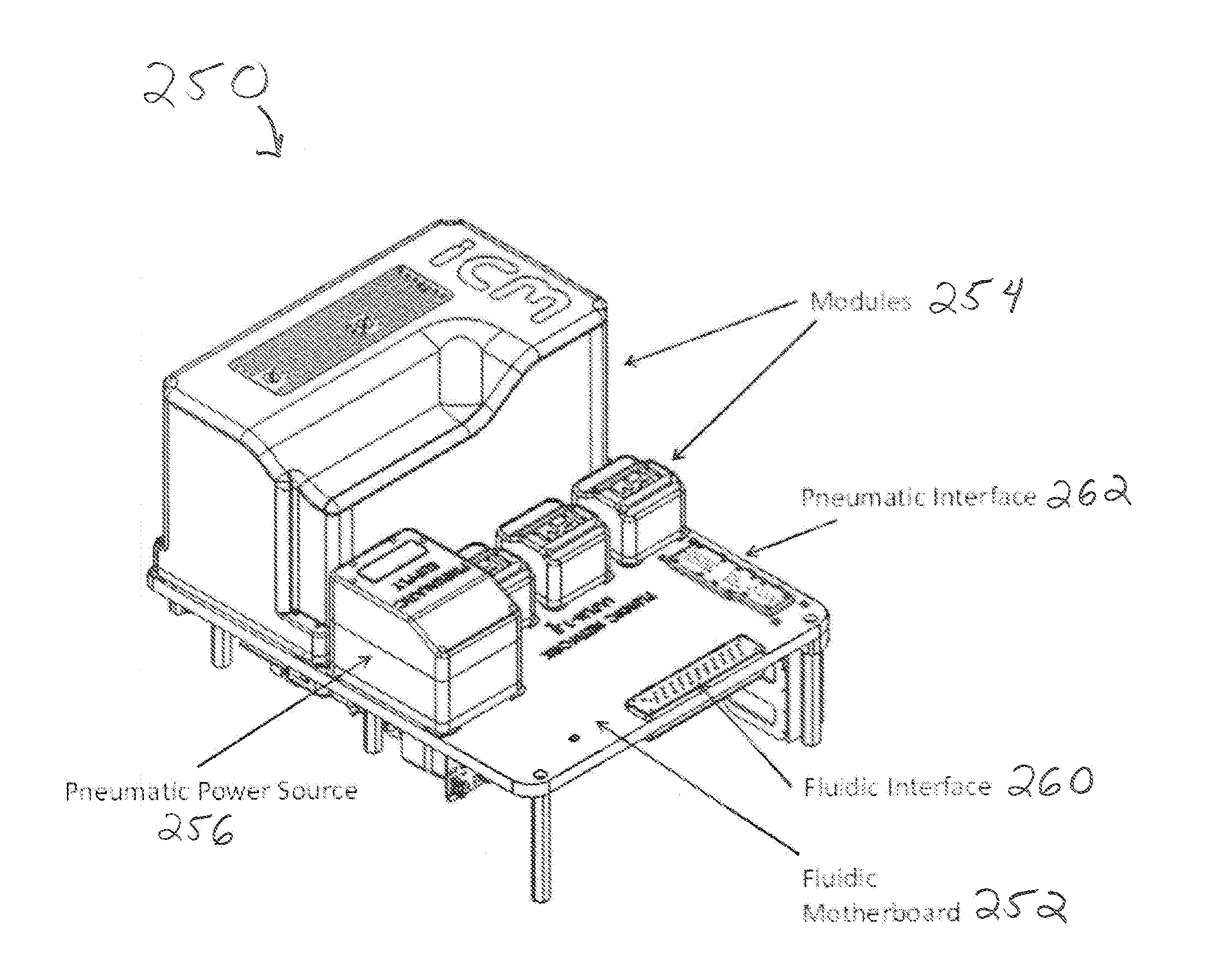
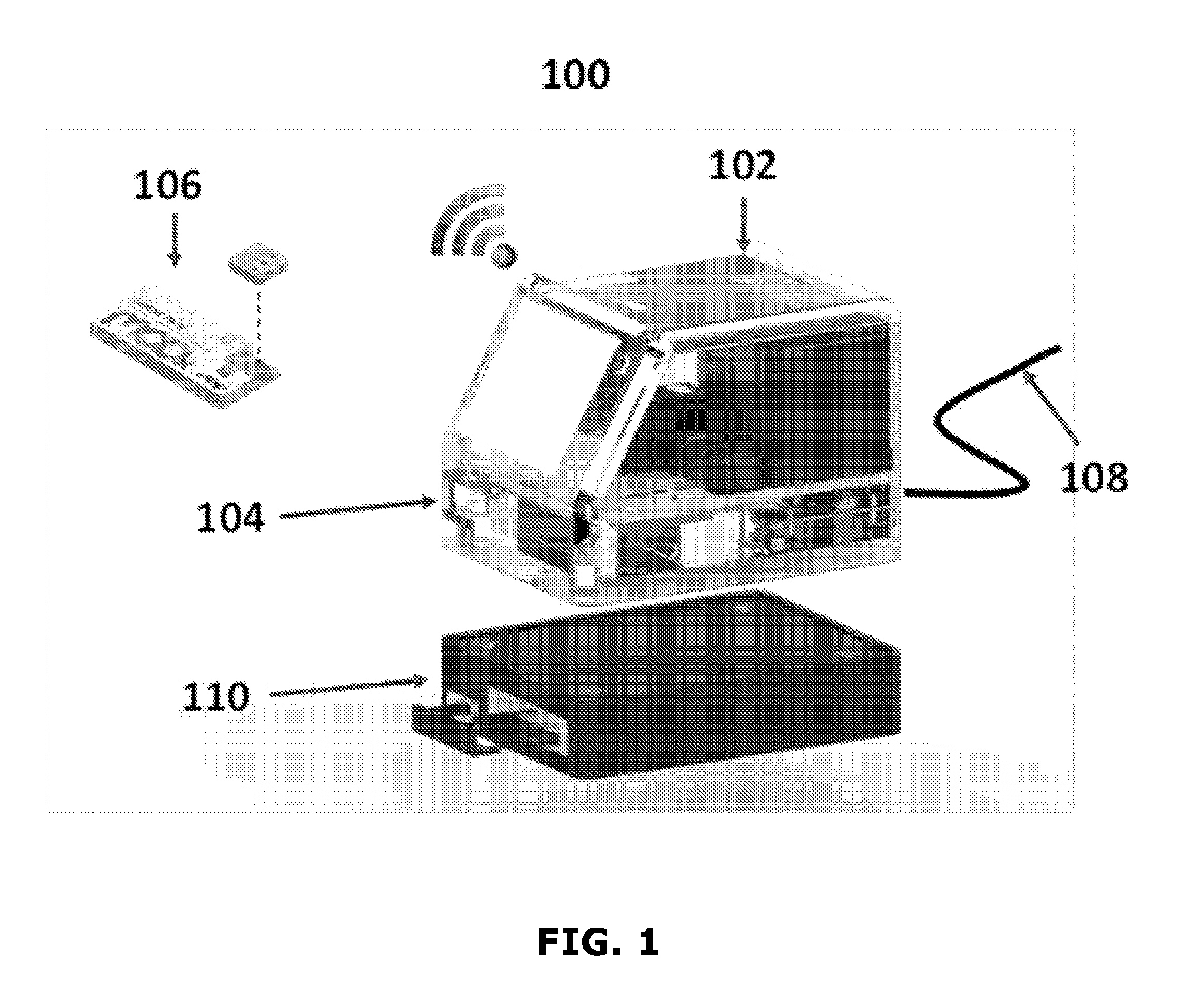
[0073]FIG. 1 shows an example of a modular analytic system 100. As illustrated, the modular analytic system 100 includes a central unit 102 which houses a fluidic network and various modular components as will be described in greater detail below.

[0074]The modular analytic system 100 is adapted to receive a number of inputs and outputs. On a front face of the central unit 102 of the modular analytic system 100, there may be a slot 104 or other type of receiving area for the selective introduction of a sample preparation unit such as the assay cartridge 106. The assay cartridge 106 may receive, contain, and store one or more samples and may receive, contain, and store one or more reagents for performing assays of the sample(s). Sample(s) may include, for example, any one of a number of types of biological fluids including, but not limited to blood, urine, saliva, and so forth. The samples and / or reagents include one or more samples and / or reagents of the same or different types. For ...


PUM

PropertyMeasurementUnit
sizeaaaaaaaaaa
sizeaaaaaaaaaa
sizeaaaaaaaaaa

Abstract

A modular analytic system includes a base, at least one fluid sample processing module configured to be removably attached to the base, at least one fluid sample analysis module configured to be removably attached to the base, a fluid actuation module positioned on the base, a fluidic network comprising multiple fluidic channels, in which the fluid actuation module is arranged to control transport of a fluid sample between the at least one sample processing module and the at least one sample analysis module through the fluidic network, and an electronic processor, in which the electronic processor is configured to control operation of the fluid actuation module and receive measurement data from the at least one fluid sample analysis module.

Description

CROSS-REFERENCE TO RELATED APPLICATION[0001]This application claims the benefit of U.S. Provisional Application No. 61 / 912,224, filed on Dec. 5, 2013, and U.S. Provisional Application No. 62 / 064,846, filed on Oct. 16, 2014. The contents of each those applications is incorporated herein by reference in its entirety.STATEMENT OF FEDERALLY SPONSORED RESEARCH OR DEVELOPMENT[0002]This invention was made with Government support under U54GM062119 and P41EB002503, awarded by the National Institutes of Health. The Government has certain rights in the invention.BACKGROUND[0003]This disclosure relates to systems for analyzing biological fluids. In particular, this disclosure relates to an analytic system in which one or more components of the system are modular in nature and connectable to a fluidic network via standardized connectors.[0004]As biological diagnostics have increased in complexity over the past decades, there has been a trend for diagnostics and testing equipment to be removed fr...

Claims


Application Information

Patent Timeline
Patent Type & Authority Applications(United States)
IPC IPC(8): B01L3/00G01N21/64G01N21/53G01N15/14G01N35/00G01N21/01
CPCB01L3/502715G01N2201/06113B01L3/502738G01N35/00871G01N21/01G01N21/532G01N15/1434G01N21/6486B01L2200/028B01L2300/0861B01L2200/027B01L2300/0832B01L2200/0689B01L2400/0487B01L2300/0627G01N2035/00881G01N2035/00326G01N2015/1006G01N2015/0065G01N2021/6493G01N2201/062B01L3/50273B01L2300/0816G01N15/12G01N15/1459G01N21/359G01N21/78G01N35/00029G01N2035/00158G01N2035/00356G01N2201/024
Inventor GRANIER, ROBERTHAGHGOOIE, RAMINKOTZ, KENPETROFSKY, ANNE C.TOMPKINS, RONALD G.
Owner THE GENERAL HOSPITAL CORP
Why Eureka
Try Eureka