Eureka AIR delivers breakthrough ideas for toughest innovation challenges, trusted by R&D personnel around the world.

Imaging Volume Data

a technology of volume data and image, applied in the field of three-dimensional (3d) image volume data, to achieve the effect of convenient and efficien

Inactive Publication Date: 2008-10-09
VOXAR +1
View PDF8 Cites 44 Cited by
  • Summary
  • Abstract
  • Description
  • Claims
  • Application Information

AI Technical Summary

Benefits of technology

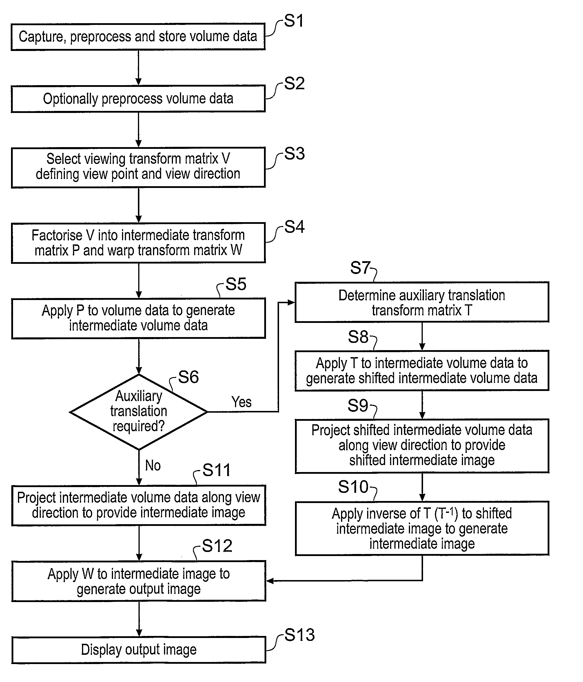
[0037]Using an intermediate mapping transform in this way, for example an intermediate transform matrix provides for a convenient and efficient algorithm for projecting the volume data.
[0038]Appropriate intermediate and warp mapping transforms can be determined by factorisation of a view mapping transform corresponding to a selected view point and view direction. This ensures the combined effect of the intermediate and warp mapping transforms provides for an output image which corresponds to the view mapping transform.
[0040]This ensures that rays cast through the volume data set during projecting pass at consistent distances from voxel centres for all view points and view directions. For example, the first and second offsets may be zero such that the centres of voxels project onto the centres of intermediate image pixels for all view points and view directions. This can assist in providing a consistent brightness to output images rendered from different view points and view directions. This can be helpful, for example, where an animated sequence of different output images of the same volume data set is to be made, for example where a user manipulates and views volume data in real time.
[0043]This approach can provide for an intermediate image which most closely matches the output image. This ensures the overall projecting conditions closely correspond with those that would be used were the output image to be conventionally rendered, e.g. with a single transform from the volume data set directly to the output image. This helps to minimise secondary artefacts that might be introduced by methods embodying the invention.

Problems solved by technology

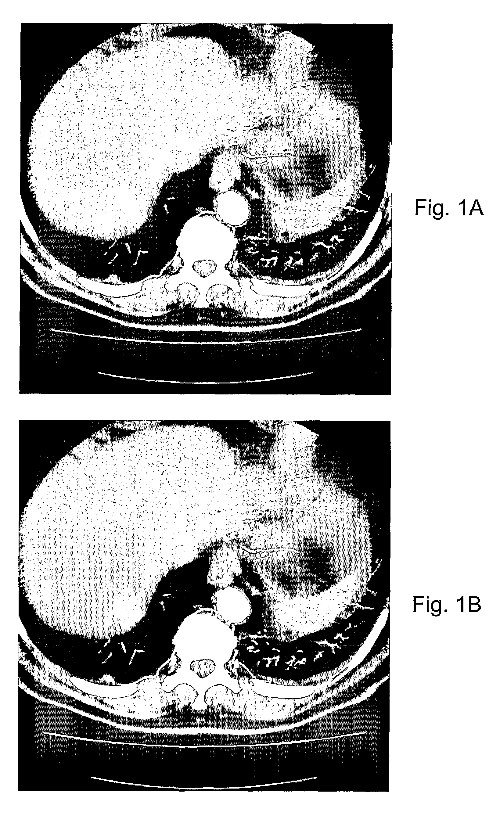
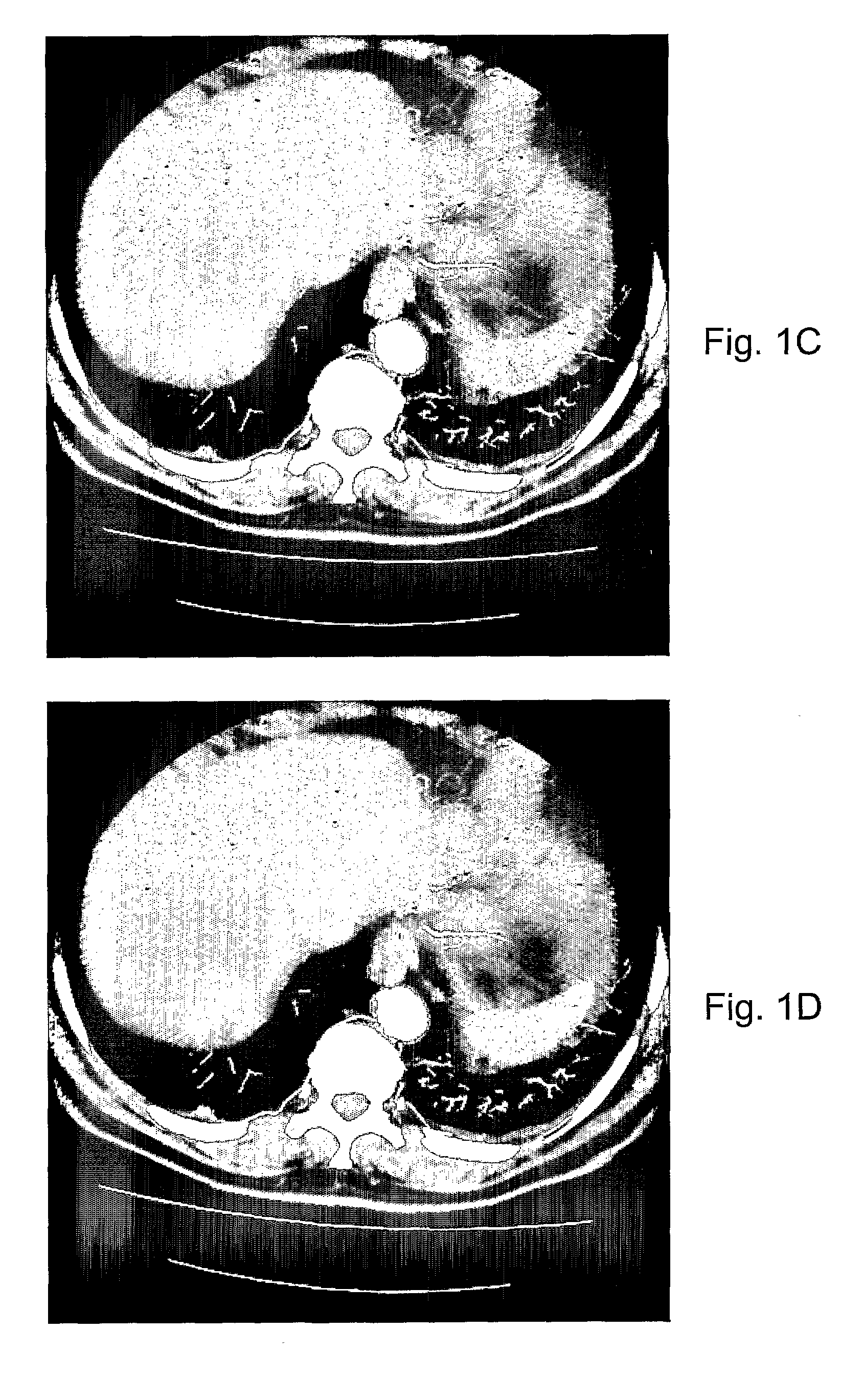
To address the problem of the hatch artefact appearing in rendered images, the first technical difficulty is to determine its cause.

Method used


Image

  • Imaging Volume Data
  • Imaging Volume Data
  • Imaging Volume Data

Examples


Embodiment Construction

[0065]FIG. 3 is an overview of the processing stages in operating an embodiment of the invention to generate a 2D output image of slab MPR volume data from a selectable view point and view direction. Slab MPR volume data are volume data comprising multiple MPR planes. The method may execute on a suitably programmed general purpose computer workstation, for example.

[0066]In step S1, raw volume data are captured by suitable capture apparatus and preprocessed and stored. The raw volume data could be captured, for example, by a computer tomographic scanner, a nuclear resonance scanner or an ultrasound scanner, etc. The data are preprocessed to generate volume data in the form of a three-dimensional array of voxel values. This may include, for example, normalisation from capture apparatus units to conventional units and mapping of data not captured on a regular voxel grid to a regular grid. The data may be stored in a random access memory of the capture apparatus for immediate further pr...


PUM


Abstract

A method and apparatus for generating a two-dimensional output image of a slab multi-planar reformatting (MPR) volume data set from a selectable view point and view direction is described. The method comprises factorising a view transform matrix into an intermediate transform matrix and a warp transform matrix. The intermediate transform matrix is such that voxels in the volume data set map to pixels in an intermediate image in which neighbouring voxels in a plane of the volume data set which is most parallel to tie plane of the output image are separated by an integer number of pixel along each of tie axes of the intermediate image. The intermediate transform matrix is applied to the data set to provide an intermediate data set. A projection of the intermediate data set along the view direction is performed according to a desired projection algorithm to provide the intermediate image. The wrap transform matrix is then applied to the intermediate image to provide the output image.

Description

BACKGROUND OF THE INVENTION[0001]The invention relates to imaging three-dimensional (3D) volume data. In particular, the invention relates to imaging of the 3D volume data with respect to a desired viewpoint and view direction.[0002]The process of calculating two-dimensional (2D) images of 3D objects is often referred to as volume rendering. Volume rendering finds applications in many fields. One such field is the rendering of medical volume data resulting, for example, from the scanning of the human or animal body using computed tomography (CT) and other X-ray scanners, nuclear magnetic resonance scanners and ultrasound scanners, to name but a few examples.[0003]The volume data generated by modern scanning equipment can be very detailed and complex to interpret. A physician may wish to render the data using different view directions and from different positions with respect to the scanned object in order to be able to analyse the scanned object and to detect, for example, abnormali...

Claims


Application Information

Patent Timeline
IPC IPC(8): G06T15/20G06T15/08
CPCG06T15/08G06T15/00G06T15/10G06T15/20
Inventor MURRAY, BENJAMIN ALAN KERRPAPAGEORGIOU, PAVLOSSMOUT, ANDREW MICHAEL CHRISTIAN
Owner VOXAR
Why Eureka
Eureka Blog
Learn More