Image processing apparatus, image forming apparatus, image processing system, and image processing method

a technology of image processing and forming apparatus, which is applied in the direction of digital data processing details, instruments, static indicating devices, etc., can solve the problems of reducing system performance, putting on an excessive workload on the control of the deletion process, and requiring a lot of time for the deletion of reference images stored in the database. , to achieve the effect of shortening the time for updating the reference image and reducing the workload

Active Publication Date: 2008-10-09
SHARP KK
View PDF8 Cites 37 Cited by
  • Summary
  • Abstract
  • Description
  • Claims
  • Application Information

AI Technical Summary

Benefits of technology

[0011]The present invention was made in view of the foregoing problems. An object of the present invention is to provide an image processing apparatus and an image processing system each of which causes identification information for identifying a reference image to be stored in a storage section in such a manner that the identification information is related to features of the reference image, the image processing apparatus and the image processing system being capable of shortening a time for updating the reference image and reducing a workload on means for updating the reference image.

Problems solved by technology

However, the technique of Patent Document 1 is problematic in that, when a document stored in the descriptor database is deleted, a deleting process requires much time and puts an excessive workload on means for the deleting process, causing a decrease in system performance.
Consequently, deletion of indices for reference images stored in the database requires much time and puts on an excessive workload on means for controlling the deletion process.
Further, since a system with a larger number of storable indices requires a database with a larger capacity, the system requires longer time for updating the database, causing a great decrease in system performance.

Method used


Image

  • Image processing apparatus, image forming apparatus, image processing system, and image processing method
  • Image processing apparatus, image forming apparatus, image processing system, and image processing method
  • Image processing apparatus, image forming apparatus, image processing system, and image processing method

Examples


embodiment 1

[0067]An embodiment of the present invention is explained below. Explained in this embodiment is a case where the present invention is applied to a digital color multi-function printer (MFP).

[0068](1-1. Arrangement of Digital Color Multi-Function Printer 1)

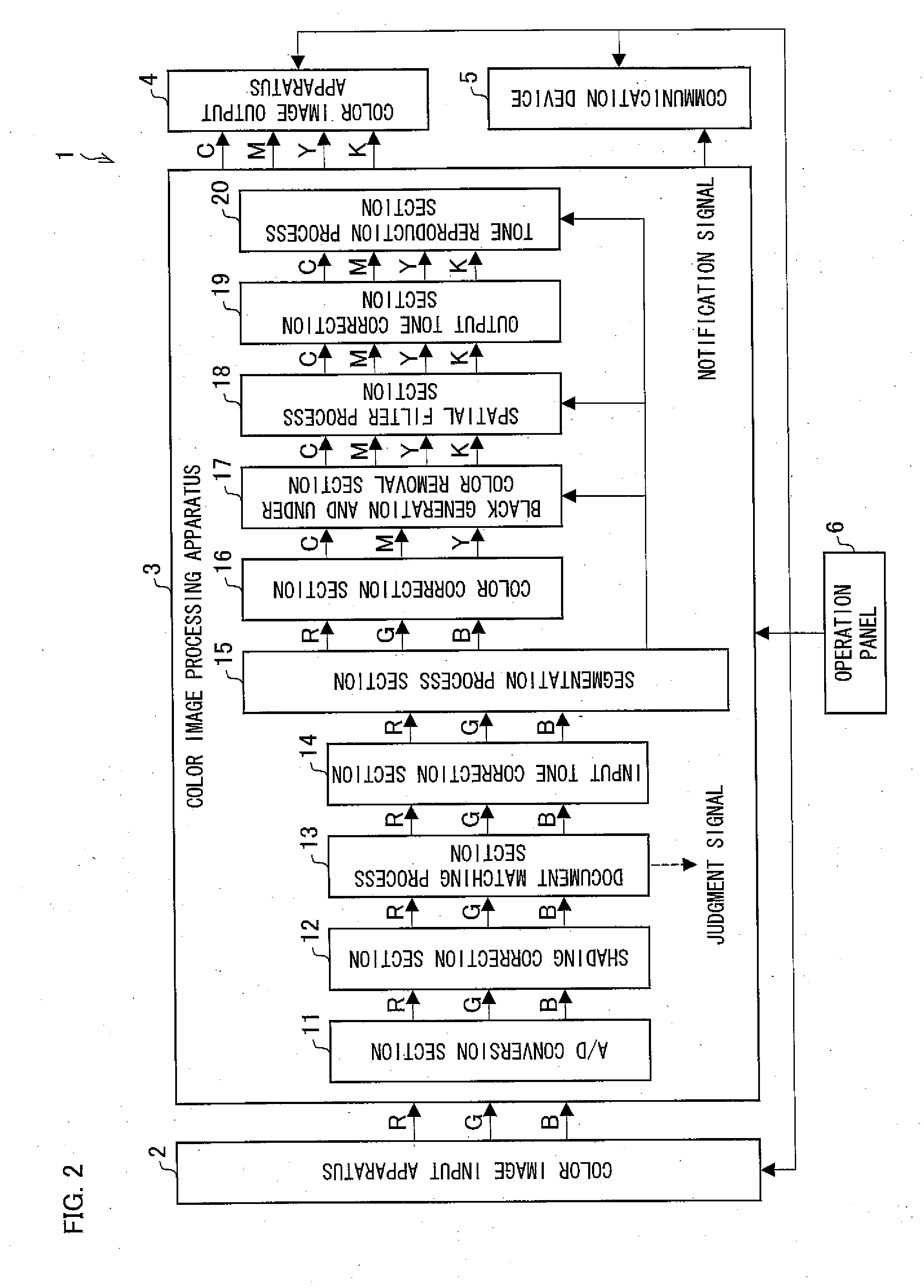
[0069]FIG. 2 is a block diagram schematically illustrating an arrangement of a digital color multi-function printer (image processing apparatus, image forming apparatus, image reading apparatus) 1 according to the present embodiment. The digital color multi-function printer 1 has a copying function, a printing function, a facsimile-transmission function, a scanning function, a scan-to-E-mail function, and the like.

[0070]As illustrated in FIG. 2, the digital color multi-function printer 1 includes a color image input apparatus 2, a color image processing apparatus 3, a color image output apparatus 4, a communication device 5, and an operation panel 6.

[0071]The color image input apparatus (image reading apparatus) 2 is, for example,...


PUM


Abstract

A reference image and features of the reference image are stored in a hash table in such a manner that the reference image and the features are related to each other. A storage region of the hash table is divided into a plurality of divided regions, and each divided region is related to a storage condition under which a reference image is stored in the divided region. When a reference image is stored in the hash table, a storage region where the reference image is to be stored is selected out of the plurality of divided regions in accordance with the storage condition. This allows shortening a time for updating a reference image, and reducing a workload on means for updating the reference image.

Description

[0001]This non-provisional application claims priority under 35 U.S.C. §119(a) on Patent Application No. 2007-102158 filed in Japan on Apr. 9, 2007 and Patent Application No. 2007-199976 filed in Japan on Jul. 31, 2007, the entire contents of which are hereby incorporated by reference.FIELD OF THE INVENTION[0002]The present invention relates to an image processing apparatus, an image forming apparatus, an image processing system, and an image processing method, each of which causes identification information for identifying a reference image to be stored in a storage section in such a manner that the identification information is related to features of the reference image.BACKGROUND OF THE INVENTION[0003]There have been proposed various techniques for comparing input image data obtained by a scanner reading a document image with a preliminarily stored image so as to determine a similarity between the document image and the preliminarily stored image.[0004]For example, Patent Documen...

Claims


Application Information

Patent Timeline
Patent Type & Authority Applications(United States)
IPC IPC(8): G06K9/60
CPCG06F17/30247H04N1/6033G06F16/583
Inventor YOSHINO, HIROKI
Owner SHARP KK
Why Eureka
Try Eureka