

Extrudable Polymer Bearing Insert
a polymer bearing and insert technology, applied in the field of sliding bearings, can solve the problems of inconvenient manufacturing and installation of polymer bearing inserts, inconvenient manufacturing of bearing inserts, and prior bearing arrangements,
- Summary
- Abstract
- Description
- Claims
- Application Information
AI Technical Summary
Benefits of technology
Problems solved by technology
Method used
Image

Examples
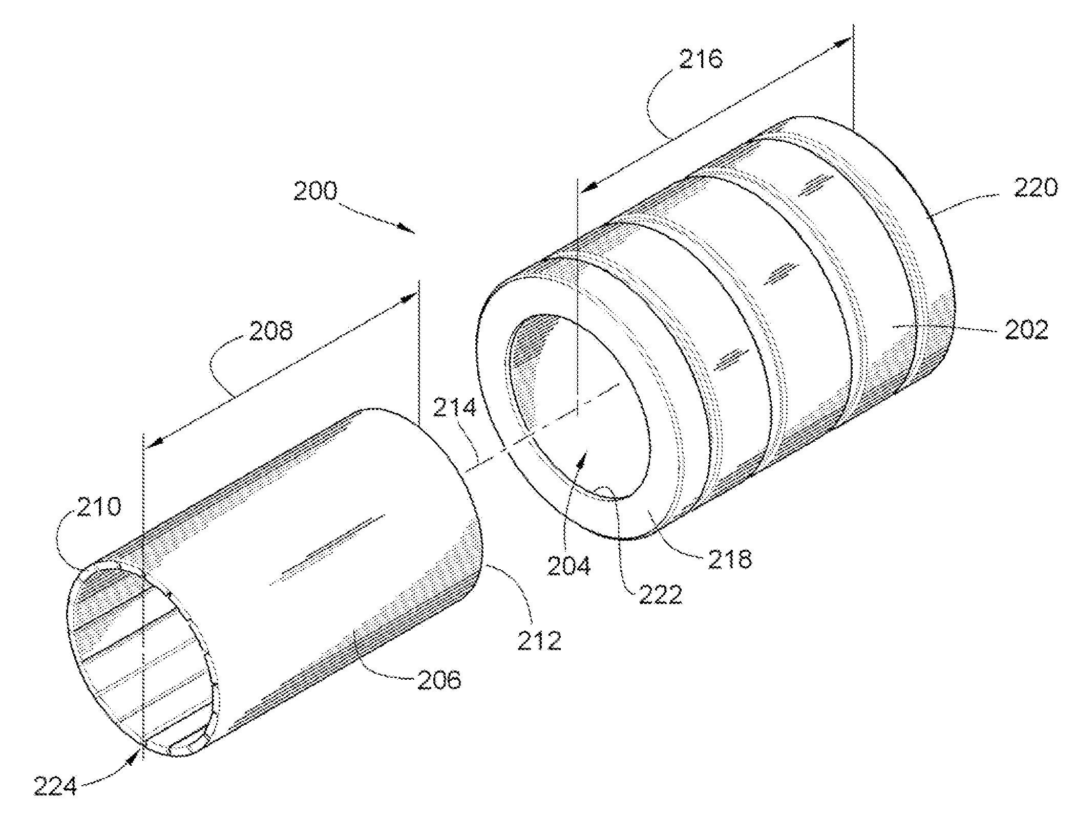
exemplary embodiment 200
[0055]The bearing insert 206 is configured to include a longitudinally extending slot 224 therein, in the same manner as described above with regard to the slot 122 in the first exemplary embodiment of the extrudable bearing insert 106. To insert the bearing insert 206 into the cylindrical opening 204 in the bearing housing 202 of the second exemplary embodiment 200 of the invention, the edges of the longitudinally extending slot 224 in the bearing insert 206 are radially offset slightly from one another, and the bearing is constricted slightly about the longitudinal axis 214, so that the bearing insert 206 may slide past the annular flange 222 at one end of the bearing housing 202 and into the interior of the bearing housing 202. Once inside the bearing housing 202, the bearing insert 206 is released and expands outward into contact with the interior wall of the housing 202 defining the cylindrical opening 204.
[0056]In embodiments of the invention subjected primarily to axial motio...
exemplary embodiment 300
[0066]The bearing insert 512, is generally similar to the bearing insert 304, described above in relation to the third exemplary embodiment 300 of the invention, with the exception that the bearing insert 512 of the fifth exemplary embodiment of the invention 500 also includes longitudinally extending first and second locating flanges 514, 516 having backsides 518, 520 thereof, extending outward from the first and second longitudinally extending edges of the insert 512 beyond the outer surface of the bearing segments of the insert 512, with the backsides 518, 520 of the locating flanges 514, 516 adapted for substantially faying contact with the first and second longitudinally extending edges 508, 510 of the slot 504 in the bearing housing 502, in the manner best illustrated in FIGS. 19, 21 and 24.
[0067]As shown in FIG. 22, the first and second longitudinally extending edges 508, 510 of the slot 504 in the housing 502 each include one or more depressions 522, which are configured to ...
exemplary embodiment 500
[0070]In forms of the invention including locating flanges, such as the flanges 514, 516 of the fifth exemplary embodiment 500 of the invention, it will be further understood that various combinations of features described hereinabove, when utilizes separately or in various combinations thereof, for retaining the insert 512 within the housing 502. For example, the bearing insert 512 may be secured within the housing 502 by use of an adhesive rather than the engagement of the deformations 524 with the depressions 522. The housing 502 may include annular flanges at opposite ends of the cylindrical opening, in some embodiments of the invention.
[0071]As shown in FIG. 26, in a sixth exemplary embodiment of a bearing apparatus 600, according to the invention, the bearing housing 602 includes an insert retaining element 601 extending inward from the inside wall of the housing 602 into the cylindrical opening 604 of the housing 602. The retaining element 601 is configured for engagement wit...
PUM
 Abstract
Description
Claims
Application Information