Remote Ultrasonic Diagnostic Subject-Side Apparatus, Remote Ultrasonic Diagnostic Examiner-Side Apparatus and Remote Ultrasonic Diagnostic System

Inactive Publication Date: 2008-10-09
KONICA MINOLTA INC
View PDF7 Cites 9 Cited by
  • Summary
  • Abstract
  • Description
  • Claims
  • Application Information

AI Technical Summary

Benefits of technology

[0037]According to the remote ultrasonic diagnostic system of the present invention, when an examiner performs a diagnosis with respect to a subject in a remote location via a communication line, an

Problems solved by technology

Moreover, there is a problem that, in a diagnosis of a circulatory system such as a heart, for example, only reproducing an image of 15 frames/second with frames reduced from the original image of 30 frames/second cannot provide necessary and sufficient image information to an examiner (medical doctor).
Thereby, a medical doctor performing an examination at a remo

Method used


Image

  • Remote Ultrasonic Diagnostic Subject-Side Apparatus, Remote Ultrasonic Diagnostic Examiner-Side Apparatus and Remote Ultrasonic Diagnostic System
  • Remote Ultrasonic Diagnostic Subject-Side Apparatus, Remote Ultrasonic Diagnostic Examiner-Side Apparatus and Remote Ultrasonic Diagnostic System
  • Remote Ultrasonic Diagnostic Subject-Side Apparatus, Remote Ultrasonic Diagnostic Examiner-Side Apparatus and Remote Ultrasonic Diagnostic System

Examples


embodiment 1

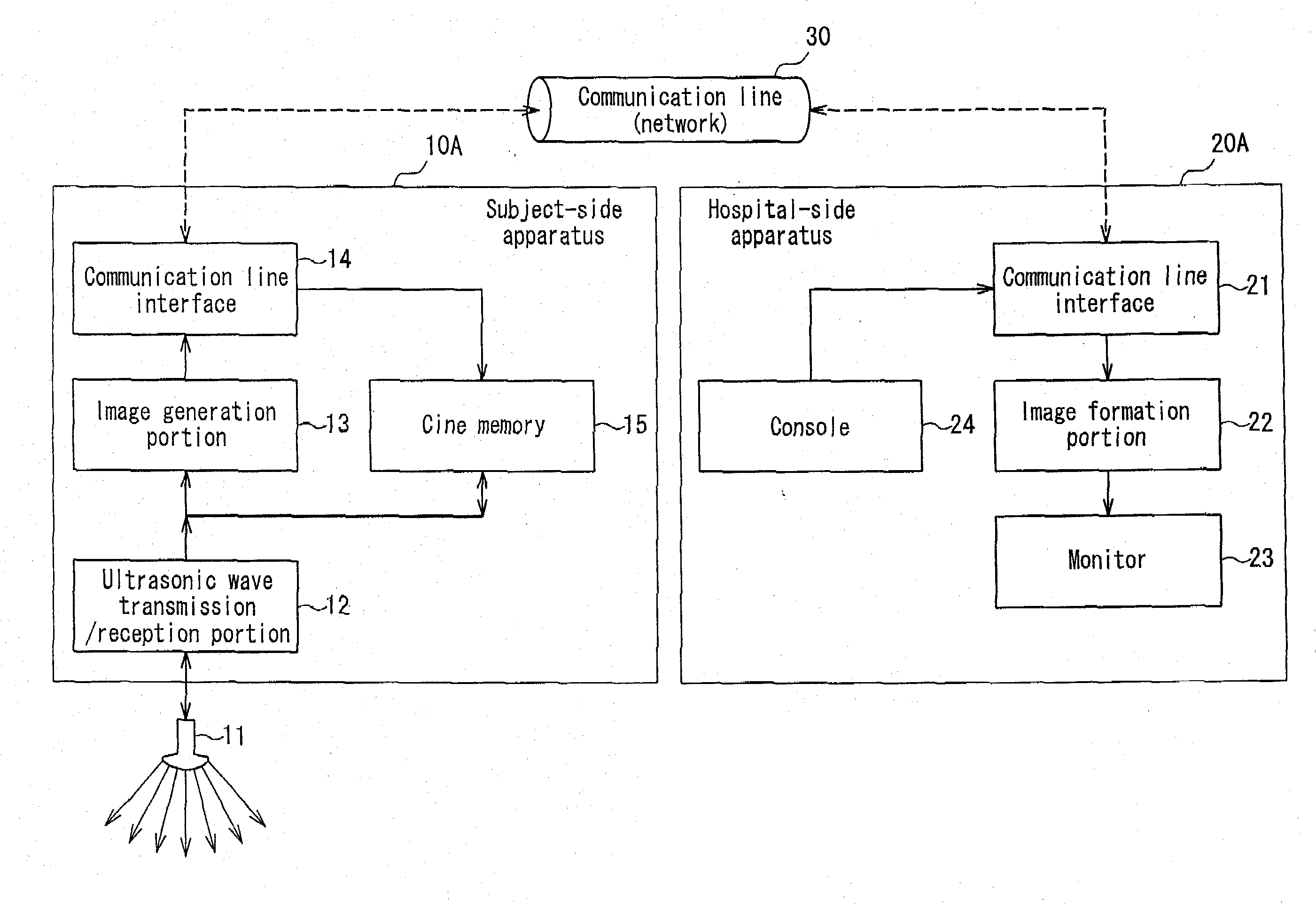
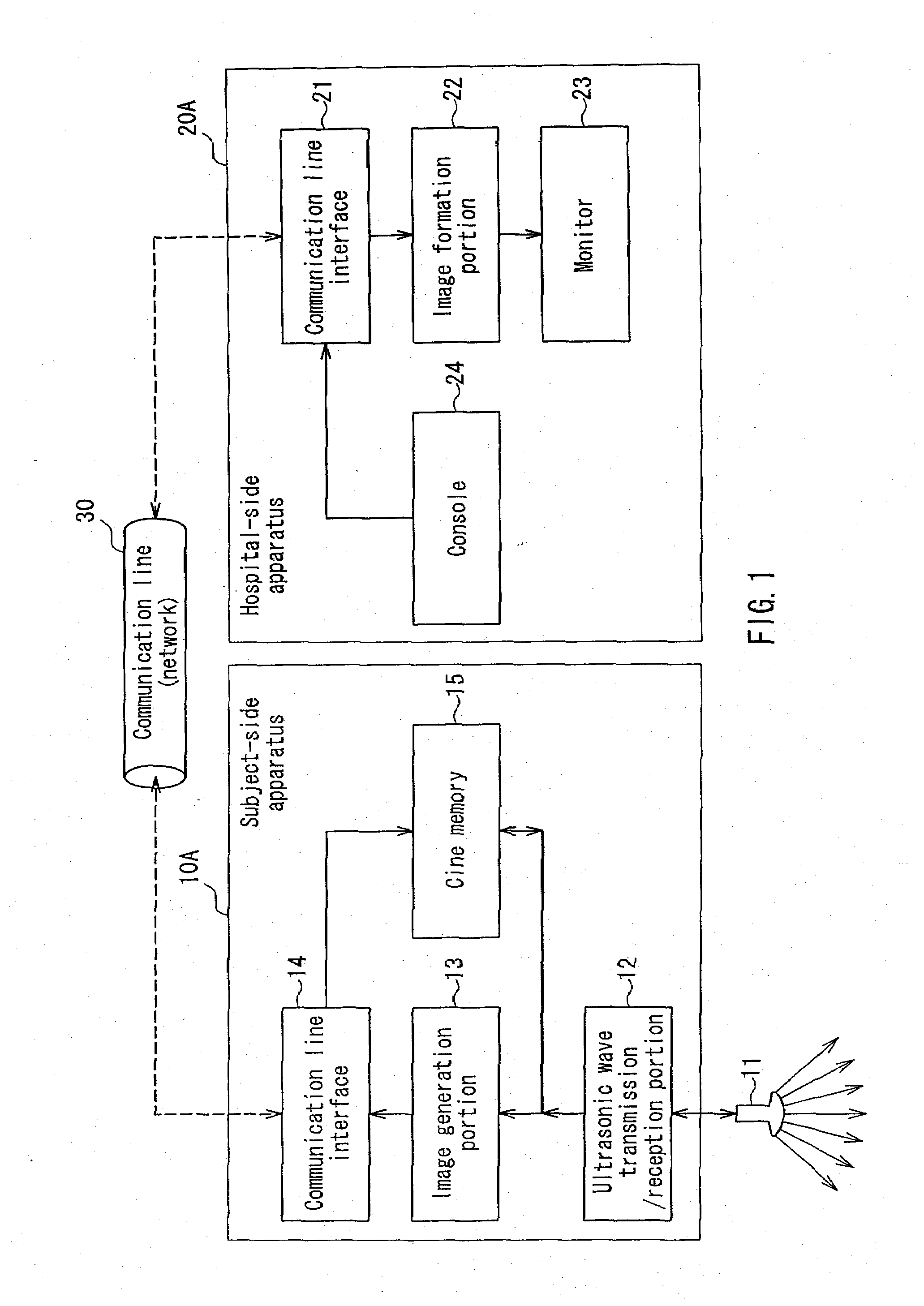
[0069]FIG. 1 is a block diagram schematically showing an example of a configuration of a remote ultrasonic diagnostic system according to Embodiment 1 of the present invention. A transmission pulse generated by an ultrasonic wave transmission / reception portion 12 in a subject-side apparatus 10A drives an ultrasonic probe 11 (electroacoustic converting means) that is connected to the subject-side apparatus 10A, and an ultrasonic signal is transmitted from the ultrasonic probe 11 into the subject and starts to receive the signal at the same time. The received ultrasonic signal is subjected to delay synthesis at the ultrasonic wave transmission / reception portion 12, and an ultrasonic image data is generated at an image generation portion 13. Moreover, an input signal to the image generation portion 13 is input also into a cine memory 15 (cine memory of the subject-side apparatus), and the cine memory 15 sequentially stores a reception signal as image information per each frame from the...

embodiment 2

[0076]FIG. 4 is a block diagram schematically showing an example of a configuration of a remote ultrasonic diagnostic system according to Embodiment 2 of the present invention. Herein, the same reference numerals are assigned to the same elements as those composing the system shown in FIG. 1 so as to simplify their explanations. In the present embodiment, a cine memory 25 (a cine memory of an examiner-side apparatus) is provided also in a hospital-side apparatus 20B.

[0077]In the system of FIG. 4, when the console 24 of the hospital-side apparatus 20B requires to freeze, an ultrasonic image displayed on the monitor 23 freezes. At the same time, the communication line interface 21 transmits freeze information to the subject-side apparatus 10A via the communication line 30, and requires to retransmit the image data accumulated in the cine memory 15, whereby the data accumulated in the cine memory 15 is transmitted to the cine memory 25 in the hospital-side apparatus 20B via the image g...

embodiment 3

[0080]FIG. 5 is a block diagram schematically showing an example of a configuration of a remote ultrasonic diagnostic system according to Embodiment 3 of the present invention. In the present embodiment, a monitor 16 (a displaying means of a subject-side apparatus) is provided also in a subject-side apparatus 10B.

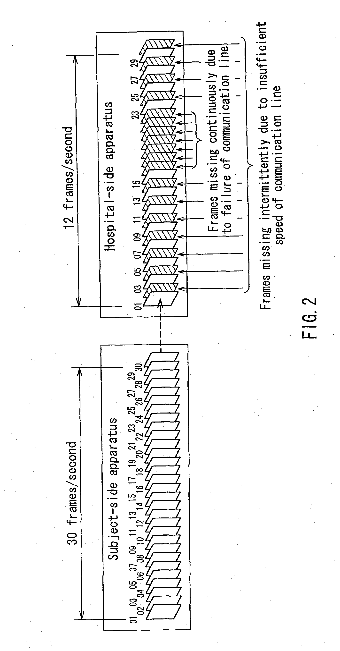
[0081]In the system of FIG. 5, similarly to Embodiment 1, in the case where the console 24 requests cine-memory reproduction, a designated frame is retransmitted from the cine memory 15 in the subject-side apparatus 10B in which an image frame is recorded to the communication line interface 21 of the hospital-side apparatus 20A without depending on a condition of the communication line 30, and is displayed on the monitor 23 via the image formation portion 22, whereby the cine memory can be reproduced without any frame missing from all of the 30 image frames per one second. At this time, the image that is transmitted to the hospital-side apparatus 20A is displayed also on th...


PUM


Abstract

A subject-side apparatus 10A is provided with a cine memory 15 for sequentially storing an ultrasonic signal that is received by an ultrasonic wave transmission/reception portion 12 per each frame. Every time after freezing when moving a pointer for designating a frame to be reproduced in a hospital-side apparatus 20A, a communication line interface 14 of the subject-side apparatus reproduces a frame that is required to be retransmitted by a console 24 of the hospital-side apparatus from the cine memory, and retransmits it to a communication line interface 21 of the hospital-side apparatus via a communication line 30. Then, an ultrasonic image of the retransmitted frame is displayed on a monitor 23. When an examiner performs a diagnosis with respect to a subject in a remote location via the communication line, an ultrasonic image can be displayed with sufficiently suppressed degradation of an image quality compared with an image quality of an original image, even at a low data rate of the communication line.

Description

TECHNICAL FIELD[0001]The present invention relates to a ultrasonic diagnostic system for medical use, and particularly relates to a remote ultrasonic diagnostic system that is capable of providing an ultrasonic image by which an examiner can perform a diagnosis, even when a subject being examined is physically remote from the examiner (medical doctor in a hospital).BACKGROUND ART[0002]According to reduction in size of an ultrasonic diagnostic apparatus that easily provides a tomographic image of a subject as a real-time ultrasonic dynamic image, the ultrasonic diagnostic apparatus plays more important roles in various medical diagnoses and examinations at the places other than ultrasonic inspection rooms, such as bedsides in hospital wards, private clinics and health care support center in the offices, for example.[0003]However, because of the limitation of the number of medical doctors as examiners who can perform diagnoses accurately from displayed ultrasonic dynamic images, the s...

Claims


Application Information

Patent Timeline
IPC IPC(8): A61B8/00A61B8/13
CPCA61B8/13A61B8/565
Inventor WATANABE, YOSHINOBUHAGIWARA, HISASHITANNAKA, YOSHINAOSUZUKI, TAKAO
Owner KONICA MINOLTA INC
Why Eureka
Try Eureka