Flexible clamp

a clamping and flexible technology, applied in the direction of snapping fasteners, heat collector mounting/support, light and heating apparatus, etc., can solve the problems of increasing the total cost of solar panel installation, increasing labor costs and related overhead, and preventing the clamp from effectively stabilizing an adjoining panel. , to achieve the effect of little separation

Inactive Publication Date: 2008-10-16
ZANTE ANTHONY A
View PDF13 Cites 42 Cited by
  • Summary
  • Abstract
  • Description
  • Claims
  • Application Information

AI Technical Summary

Benefits of technology

[0027]It is another object of the present invention to provide a new and improved flexible clamp that allows compression of the flexible clamp within a space to provide as little separation between the clamped objects as possible.
[0028]A further object or feature of the present invention is a new and improved flexible clamp that allows the secure fixation of materials of differing thicknesses.

Problems solved by technology

However, when employed in the field an installer normally needs both hands free to position the panel and cannot simultaneously raise the clamp's capturing flange while also positioning the panel for attachment.
This necessitates the help of an assistant, increasing labor costs and related overhead, and thereby increasing the total costs for the installation of a solar panel system.
While good in concept, in practice panels may have small variations in edge thickness that may either cause the clip to be too short, thereby requiring the clip be lifted, or too long, which prevents the clip from effectively stabilizing an adjoining panel.
When so installed, however, it places a stress on the line of contact on the clamped member.
Notably, most single piece clamps simply cannot be adjusted in height while simultaneously maintaining a proper angular position on the part being clamped.
The “C-clip,” however, has a wide profile due to the arcuate configuration of its side element, and it thus requires additional space between panels for installation.
Other methods have been developed to hold clamps in a raised condition including springs or retaining clips, but these solutions add components, thus complicating the clamping process and increasing the overall cost of clamping materials and labor.

Method used


Image

  • Flexible clamp
  • Flexible clamp
  • Flexible clamp

Examples


Embodiment Construction

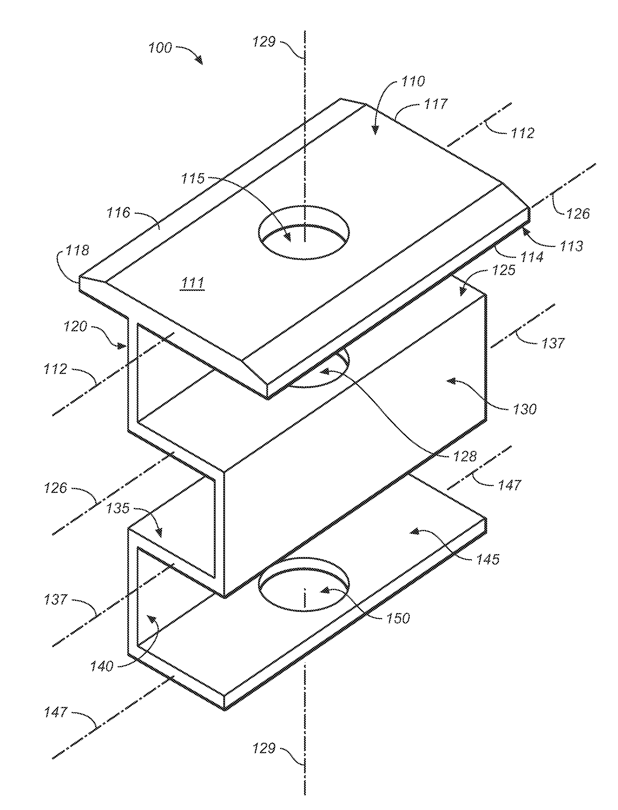
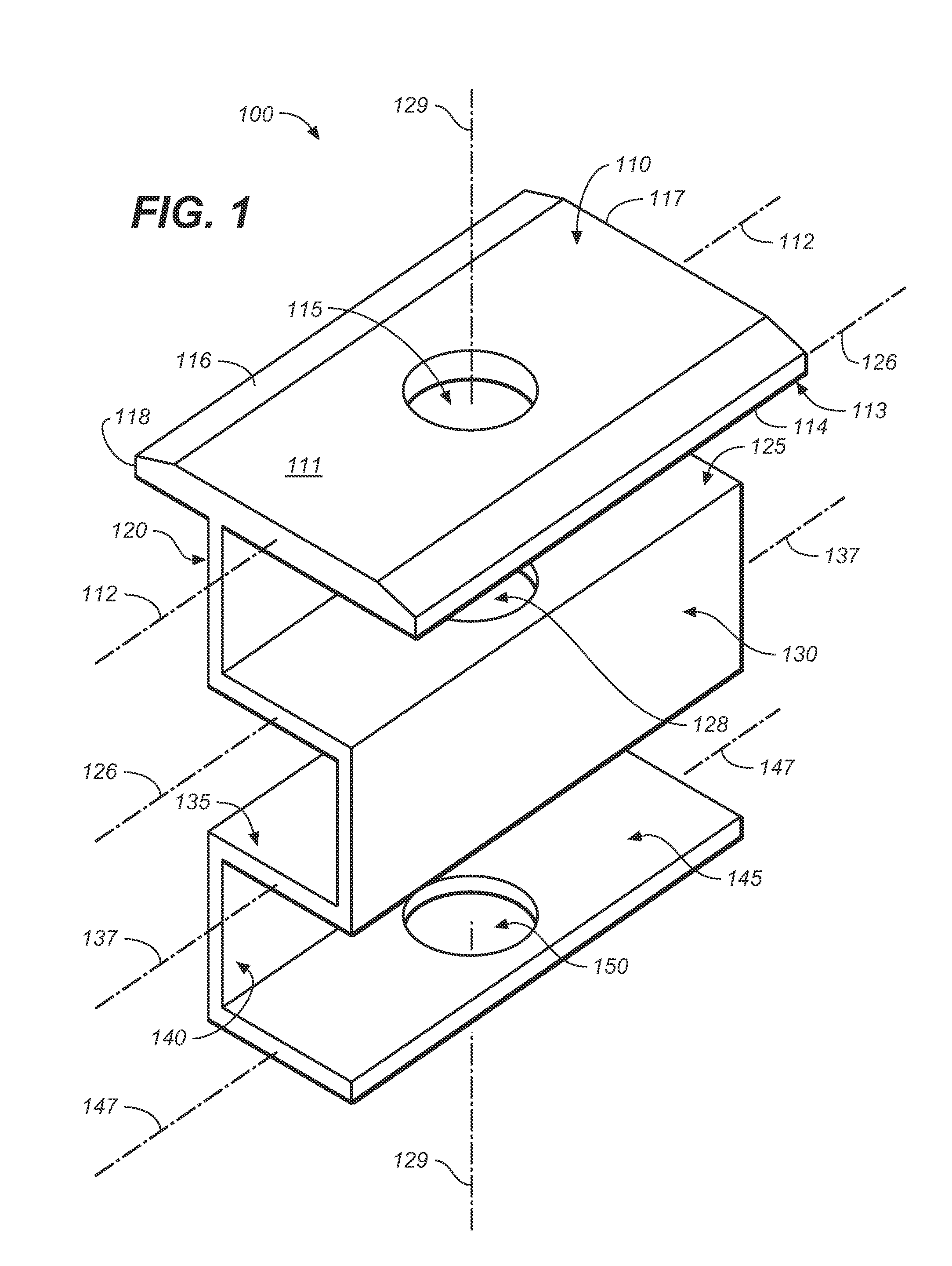
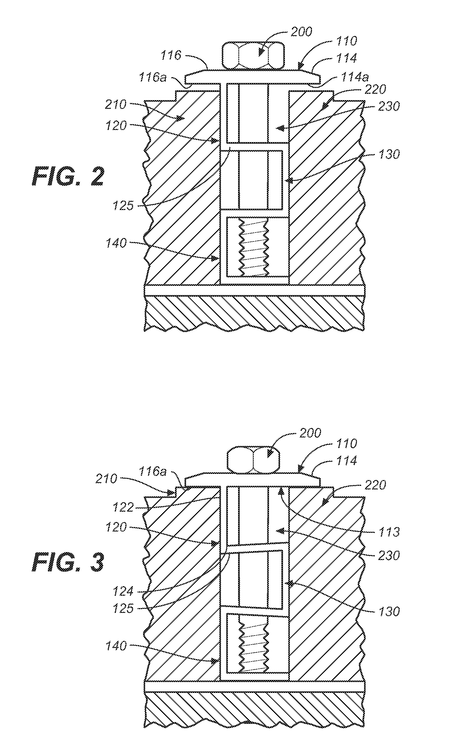
[0050]Referring to FIGS. 1 through 3, wherein like reference numerals refer to like components in the various views, there is illustrated therein a new and improved flexible clamp, generally denominated 100 herein.

[0051]FIG. 1 illustrates a first preferred embodiment of the inventive flexible clamp 100. The flexible clamp 100 has a flat captive flange 110 forming the top portion of the device. The captive flange 110 is generally rectangular in shape, having a longitudinal axis 111, a top face 112, a bottom face 113, a left side 114, a right side 116, a rear side 117, and a front side 118. A circular first bolt aperture 115 is located centrally in the captive flange 110 generally on the longitudinal axis 111. Extending perpendicularly, and medially to the captive flange longitudinal axis is a first vertical member 120, having a top edge 122 and a bottom edge 124. The top edge of the first vertical face 120 is attached to the bottom face 113 of the captive flange 110, slightly right o...


PUM


Abstract

A flexible clamp for clamping and spacing solar panel modules, including a captive flange forming a top portion, which includes a top face, a bottom face, a right side, a left side, a front side, a back side, a substantially planar underside to engage the modules upper surface. It also includes a longitudinal axis and an aperture disposed generally along that axis. First, second, and third horizontal members are disposed under the captive flange and include substantially planar surfaces generally parallel to the underside of the captive flange. Each horizontal member includes a right side, a left side, a front side, a back side, a width slightly less than the width of the captive flange, and an aperture coaxial with the aperture in the captive flange. A first vertical member connects the right side of the first horizontal member with the captive flange at a point slight right of the longitudinal axis and left of the right side, thus forming a right overhang for engaging a first solar panel. A second vertical member connects the left sides of the second and third horizontal members in such manner that a left overhang is formed, and this is adapted for engaging a second solar panel adjacent to the first panel. A third vertical member coplanar with the first vertical member connects the right sides of the second and third horizontal members. When a bolt is passed through the coaxial apertures and tightened, the clamp flexes and bows slightly outwardly.

Description

CROSS REFERENCES TO RELATED APPLICATIONS[0001]The present application claims the benefit of the filing date of U.S. Provisional Patent Application Ser. No. 60 / 911,134, filed Apr. 11, 2007 (Apr. 11, 2007).STATEMENT REGARDING FEDERALLY SPONSORED RESEARCH OR DEVELOPMENT[0002]Not applicable.THE NAMES OR PARTIES TO A JOINT RESEARCH AGREEMENT[0003]Not applicable.INCORPORATION-BY-REFERENCE OF MATERIAL SUBMITTED ON A COMPACT DISC[0004]Not applicable.BACKGROUND OF THE INVENTION[0005]1. Field of the Invention[0006]The present invention relates generally to flexible clamps, and more particularly to a flexible clamp adapted to affix adjoining structures in a coplanar fashion. It accomplishes this through a flexible compression of the clamp so as to engage a flange upon the planar structures and engagement of the sides on the clamp with the surface of a frame channel.[0007]2. Discussion of Related Art Including Information Disclosed Under 37 CFR §1.97, 1.98[0008]Clamping devices are well known a...

Claims


Application Information

Patent Timeline
Patent Type & Authority Applications(United States)
IPC IPC(8): A44B21/00A44B99/00
CPCF16B5/0657F16B13/061F24J2/5258Y10T24/44744Y02E10/47Y02B10/12H02S20/23F24J2002/4683F24S25/636F24S2080/01Y02B10/10Y02E10/50
Inventor ZANTE, ANTHONY A.
Owner ZANTE ANTHONY A
Why Eureka
Try Eureka