Viewing device comprising a pupil expander including two mirrors

Active Publication Date: 2020-08-20
THALES SA
View PDF0 Cites 3 Cited by
  • Summary
  • Abstract
  • Description
  • Claims
  • Application Information

AI Technical Summary

Benefits of technology

[0024]Advantageously, for any inclination of the light beams output from the optical assembly, the separation between a beam propagating through the light guide and the

Problems solved by technology

The main drawback of this solution is that, by construction, the eye of the observer is located far from the pupil of the system.
The preceding limitation disappears and the instantaneous field of observation is now only limited by the dimensions of the optical combiner.
However, this solution has other drawbacks.
The steering optic and the combiner are complex to produce.
In the end, a syste

Method used


Image

  • Viewing device comprising a pupil expander including two mirrors
  • Viewing device comprising a pupil expander including two mirrors
  • Viewing device comprising a pupil expander including two mirrors

Examples


Example

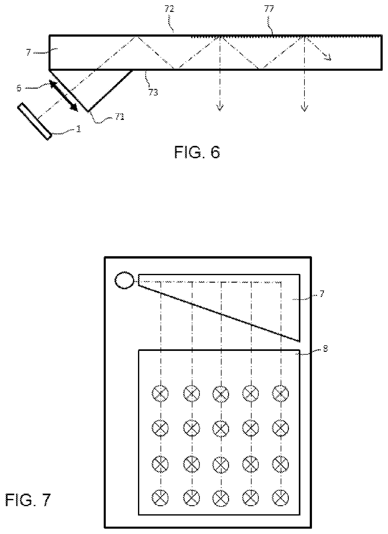
[0042]FIG. 10 shows the principle of a pupil-expansion viewing device according to the invention. In the case of FIG. 10, the pupil expansion is performed in a single direction. As will be seen, it is possible to perform this expansion in two different directions.

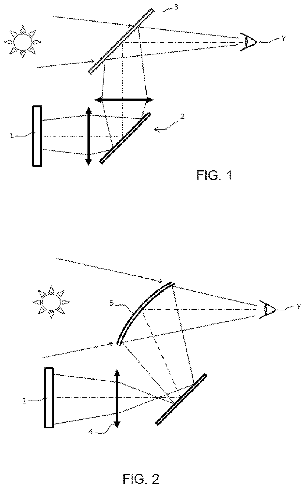
[0043]This viewing device comprises a collimating optical assembly and a light guide. The optical assembly comprises a display 1 and an optical system 6 that forms of this display an image at infinity. The display may be of any nature. In particular, the device works with all types of polychromatic display.

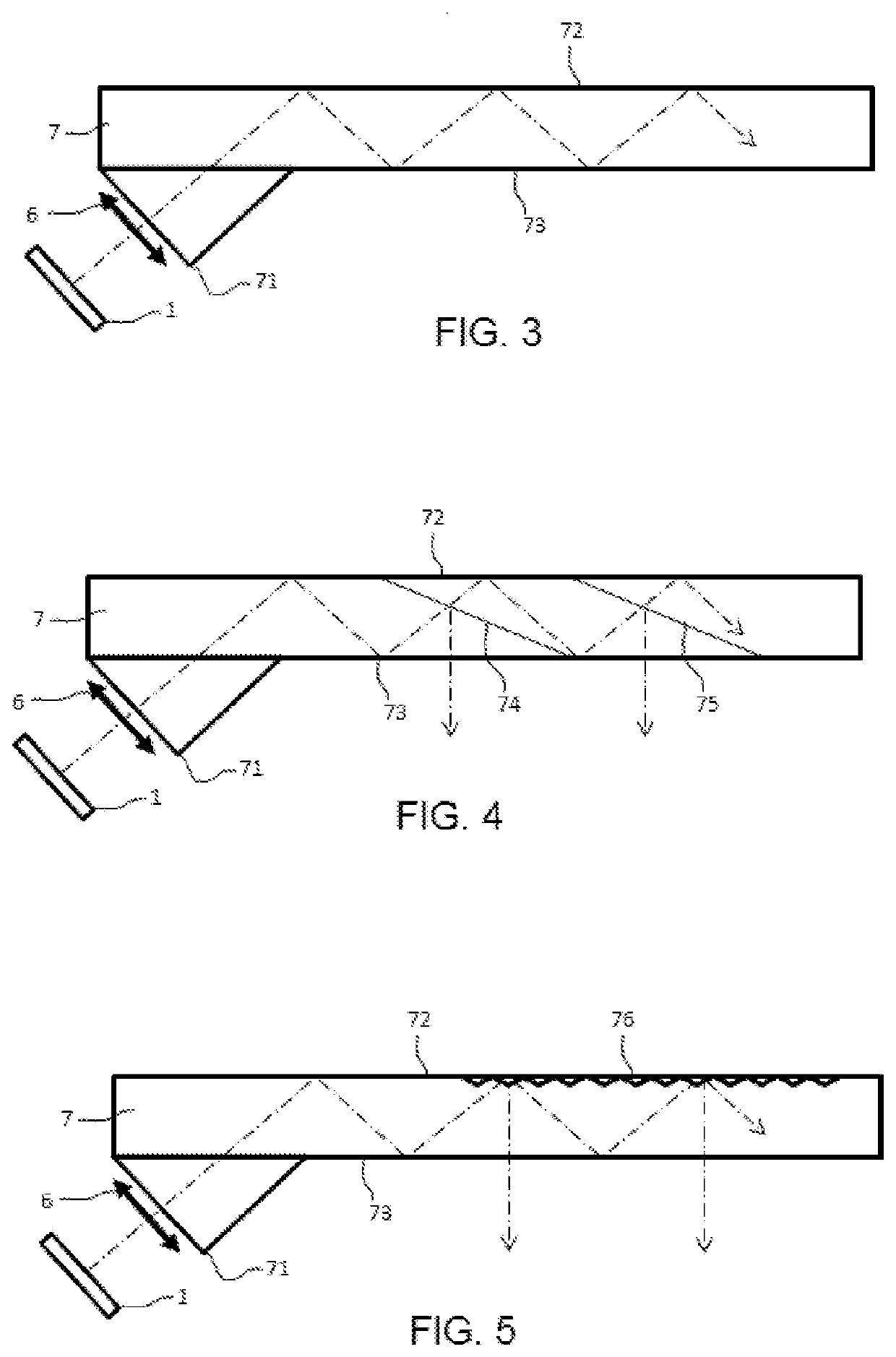
[0044]The light guide comprises a planar mirror 20 and a semi-reflective plate 21 parallel to the planar mirror, the optical axis of the optical assembly being inclined with respect to the surface of the planar mirror by an angle α.

[0045]Below, by semi-reflective plate what is meant is an optical plate that is partially reflective, that comprises a treatment that transmits some of the incident light and that reflects the ...


PUM


Abstract

A viewing devices includes an optical assembly comprising a display, an optical system forming of this display an image at infinity and a light guide for expanding a pupil in two spatial directions. The guide comprises three planar mirrors and two semi-reflective plates, the optical axis of the optical assembly being inclined with respect to the surface of the first planar mirror by an angle different from zero and strictly smaller than 90 degrees, the light beams output from the optical assembly propagating inside the light guide via successive reflections from the planar mirrors and the semi-reflective plates, the transmission of the light beams output from the optical assembly to outside of the light guide occurring via successive transmissions by the second semi-reflective plate.

Description

CROSS-REFERENCE TO RELATED APPLICATIONS[0001]This application claims priority to foreign French patent application No. FR 1901468, filed on Feb. 14, 2019, the disclosure of which is incorporated by reference in its entirety.FIELD OF THE INVENTION[0002]The general technical field of the invention is that of viewing systems that allow an image generated by a viewing device to be superposed on the exterior. These devices are used in various fields of application. These devices may be fastened to a structure such as a vehicle dashboard or an aeronautical instrument panel. Head-up displays (HUD) are then spoken of. They may also be mounted on a carrier worn on the head of the user. They are then known as helmet mounted displays (HMD).BACKGROUND[0003]FIG. 1 shows a first architecture allowing this type of viewing system to be achieved. In this figure and the following, optical components have been drawn with thick solid lines and light rays with thin or dashed lines. Optics containing len...

Claims


Application Information

Patent Timeline
IPC IPC(8): G02B27/01
CPCG02B2027/0118G02B27/0172G02B27/0101G02B2027/0123G02B27/0081G02B27/148
Inventor DAMAMME, NATACHABARDON, JEAN-LUCBOURGAIN, JEAN-LOUISCONI, PHILIPPE
Owner THALES SA
Why Eureka
Try Eureka