Color display device and method utilizing convergence correction

a color display device and convergence correction technology, applied in the field of color display, can solve the problems of reducing the accuracy of convergence correction around the perimeter of the screen, reducing and the size of the circuit required

Inactive Publication Date: 2006-04-25
HITACHI LTD
View PDF19 Cites 4 Cited by
  • Summary
  • Abstract
  • Description
  • Claims
  • Application Information

AI Technical Summary

Benefits of technology

[0011]In accordance with the invention, a color display device includes a convergence apparatus having digital convergence correction data. The data are converted to an analog signal which is used as a convergence correction signal. In one aspect of the invention, the digital convergence correction data are supplied to circuitry of the convergence apparatus at a varying data rate. The digital convergence correction data correspond to correction points located on the display screen. Separation of correction points in an edge portion of the display screen is smaller that separation of correction points in a center portion of the display screen.

Problems solved by technology

For example, the following problem arises: influence of the correction data outside the screen causes a correction waveform in proximity to a starting position of the display range to become smaller than correction data in proximity to its position, resulting in decrease in accuracy of the convergence correction around the perimeter of the screen.
Therefore, there is a possibility of decreasing accuracy of the convergence correction in proximity to the perimeter of the screen.
However, if the number of n is doubled, labor at the time of the manual adjustment, the required size of a circuit, and memory capacity will increase greatly, which is not desirable.

Method used


Image

  • Color display device and method utilizing convergence correction
  • Color display device and method utilizing convergence correction
  • Color display device and method utilizing convergence correction

Examples


first embodiment

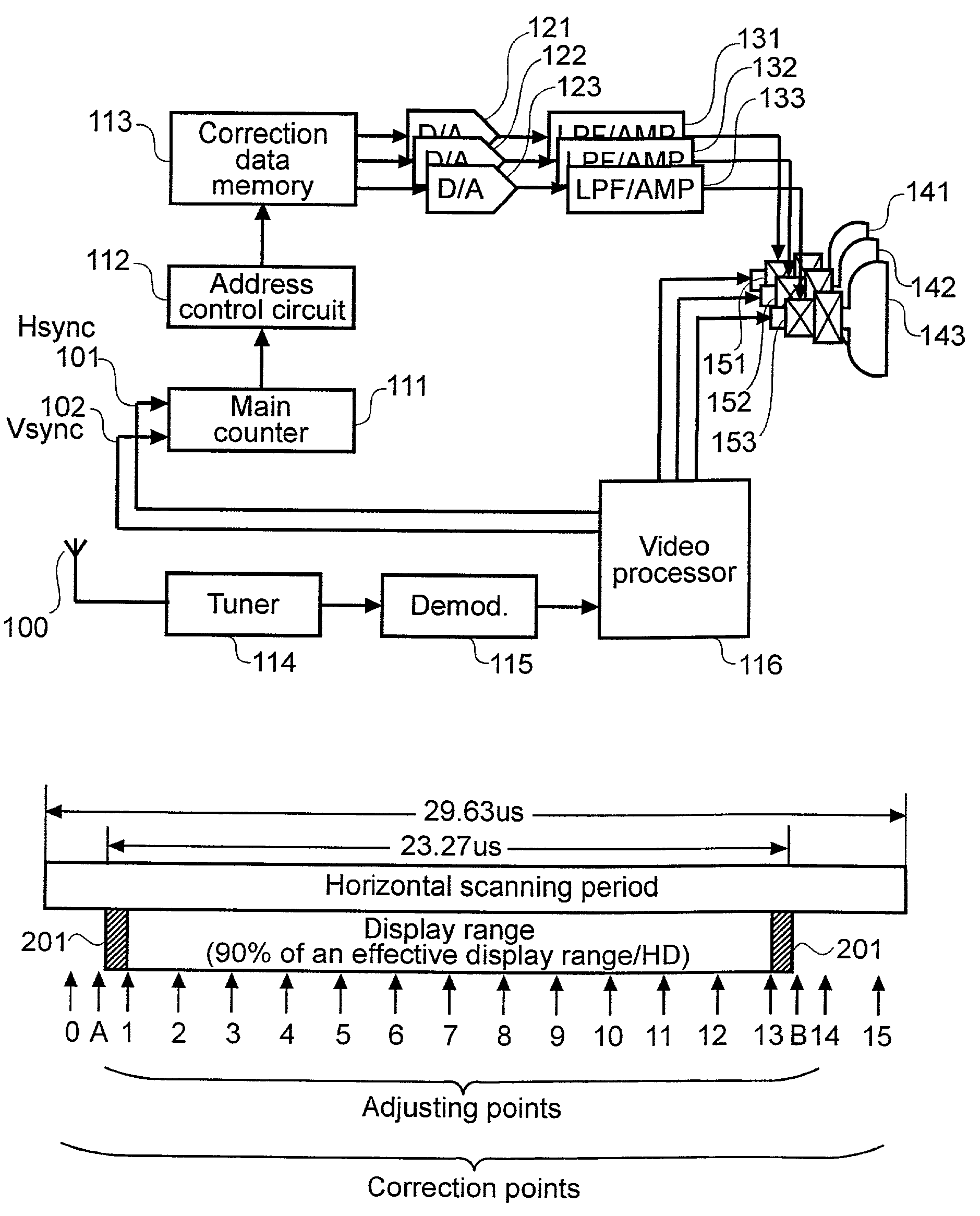
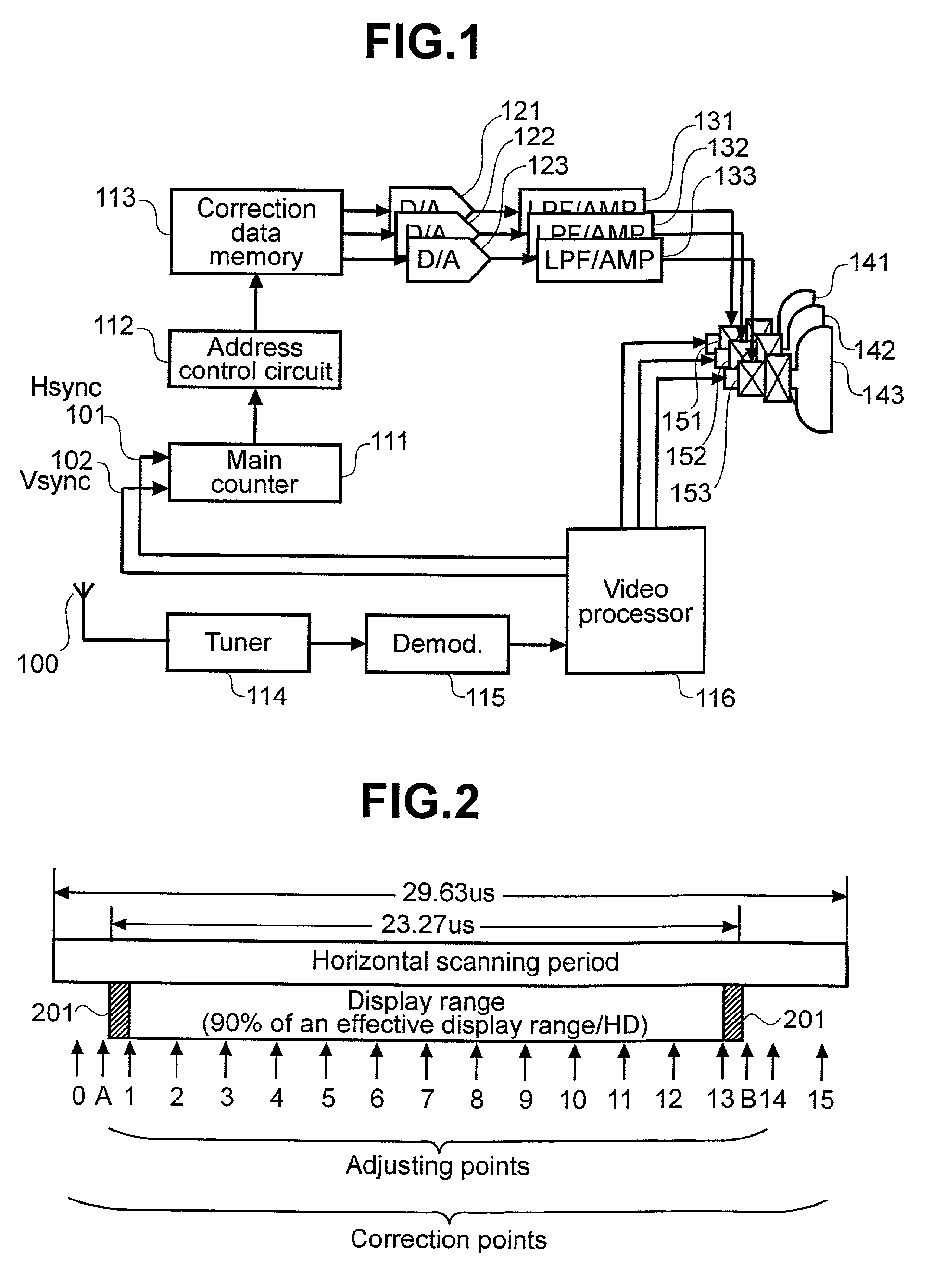
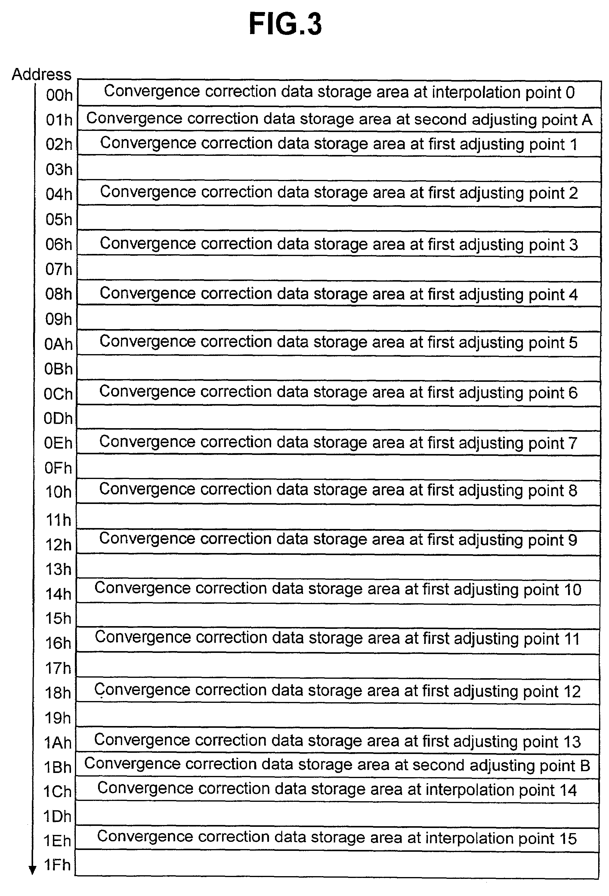
[0038]The convergence correction data for 18 points in total, which includes the first adjusting points, the interpolation points, and the second adjusting points, are prepared in the correction data memory 113 beforehand. FIG. 3 shows a first embodiment related to a memory map corresponding to one horizontal scan line in the correction data memory 113. In the memory map shown in FIG. 3, the digital correction data is stored in the correction data memory 113 while keeping positional relationships among the first adjusting point, the interpolation point, and the second adjusting point in correspondence with a horizontal scan line. In addition, as can be seen, the memory location spacing between pairs of adjacent correction data vary. Some pairs of adjacent correction data are separated by zero memory locations (e.g., data at locations 00h and 01h). Other pairs of adjacent correction data are separated by one memory location (e.g., data at locations 02h and 03h). To be more specific, ...

second embodiment

[0040]FIG. 4 shows a second embodiment related to a memory map (for one horizontal scan line) in the correction data memory 113. As regards a memory map shown in FIG. 4, the convergence correction data is stored in the first storage area of the correction data memory 113 (an area indicated by addresses 00h through 0Fh in FIG. 4) while keeping only positional relations of the first adjusting point and the interpolation point in the horizontal scan line. In addition, the second storage area (an area indicated by addresses 10h and 11h in FIG. 4) is reserved for convergence correction data of the second adjusting point. Using such a memory map permits memory capacity to be reduced to a required minimum. As compared with the conventional method, an increase in quantity is little. However, in this case, it is required to generate an address signal, which adapts to the memory map shown in FIG. 4, using the address control circuit 112. For example, when scanning of a horizontal electron bea...


PUM


Abstract

In a color display device, apparatus and method are provided to produce a convergence correction signal based on digital convergence correction values. The data rate by which the data is supplied to the apparatus varies, depending on the area of the display corresponding to the digital convergence correction values being supplied.

Description

[0001]This application is related to and claims priority from Japanese Patent Application No. 2001-190591, filed on Jun. 25, 2001.STATEMENT AS TO RIGHTS TO INVENTIONS MADE UNDER FEDERALLY SPONSORED RESEARCH OR DEVELOPMENT[0002]Not ApplicableREFERENCE TO A “SEQUENCE LISTING,” A TABLE, OR A COMPUTER PROGRAM LISTING APPENDIX SUBMITTED ON A COMPACT DISK.[0003]Not ApplicableBACKGROUND OF THE INVENTION[0004]The present invention relates generally to a color display. More specifically, the invention is directed to a digital convergence apparatus for use in color projection-type television display systems.[0005]As a prior art related to improvement in accuracy of convergence correction around the perimeter of a screen, for example, that described in Japanese Patent Laid-open No. Sho 60-185482 is known. This prior art is devised as follows: in a device that stores correction data corresponding to correction points, which are placed inside the displayed portion (herein referred to as the “dis...

Claims


Application Information

Patent Timeline
Patent Type & Authority Patents(United States)
IPC IPC(8): H04N3/22H04N3/223H04N3/227H04N3/26H04N9/28H04N9/31
CPCH04N9/28
Inventor YOSHIZAWA, KAZUHIKOWATANABE, TOSHIMITSUMATSUMI, KUNINORI
Owner HITACHI LTD
Why Eureka
Try Eureka