Enhancements to High Efficiency Hydro-mechanical Vehicle Transmission

a transmission device and high-efficiency technology, applied in the direction of fluid couplings, gearings, couplings, etc., can solve the problems of inability to successfully apply road vehicles, noise and reliability, efficiency, cost, etc., and achieve the effects of improving efficiency, high torque, and improving packing density

Inactive Publication Date: 2015-05-21
LLOYD ROBERT HUGH FRANCIS
View PDF2 Cites 4 Cited by
  • Summary
  • Abstract
  • Description
  • Claims
  • Application Information

AI Technical Summary

Benefits of technology

[0007]3, The gears of 2 above also allows the input and output pump / motors to be interleaved for improved packing density.
[0008]4, A novel design of a selectable one-way clutch allows the interleaving of 3 above. This clutch allows all the hydraulic motors to participate in the initial acceleration of the vehicle, providing a high level of torque and also as an all mechanical bypass of the hydraulic transmission for improved efficiency.
[0009]5, The large number of pump / motors allows for very small separation between the various “gears” which in turn allows the use of a very small accumulator to absorb the shifting shock and eliminates the necessity of a reservoir. This facilitates the use of the transmission as a conventional transmission (as a quasi-continuously variable transmission) without necessarily implementing regenerative braking.
[0010]6, An arrangement is disclosed where two adjacent pump / motors share a port to reduce the size of the combination allowing more power handling capability in the same physical volume.

Problems solved by technology

None of them have been successfully applied to road vehicles due to problems associated with the variable displacement devices.
These problems relate to efficiency, cost, form factor, noise and reliability.

Method used


Image

  • Enhancements to High Efficiency Hydro-mechanical Vehicle Transmission
  • Enhancements to High Efficiency Hydro-mechanical Vehicle Transmission
  • Enhancements to High Efficiency Hydro-mechanical Vehicle Transmission

Examples


Embodiment Construction

[0017]In this description, the term pump / motor refers to hydraulic devices that can function either as a hydraulic pump or hydraulic motor.

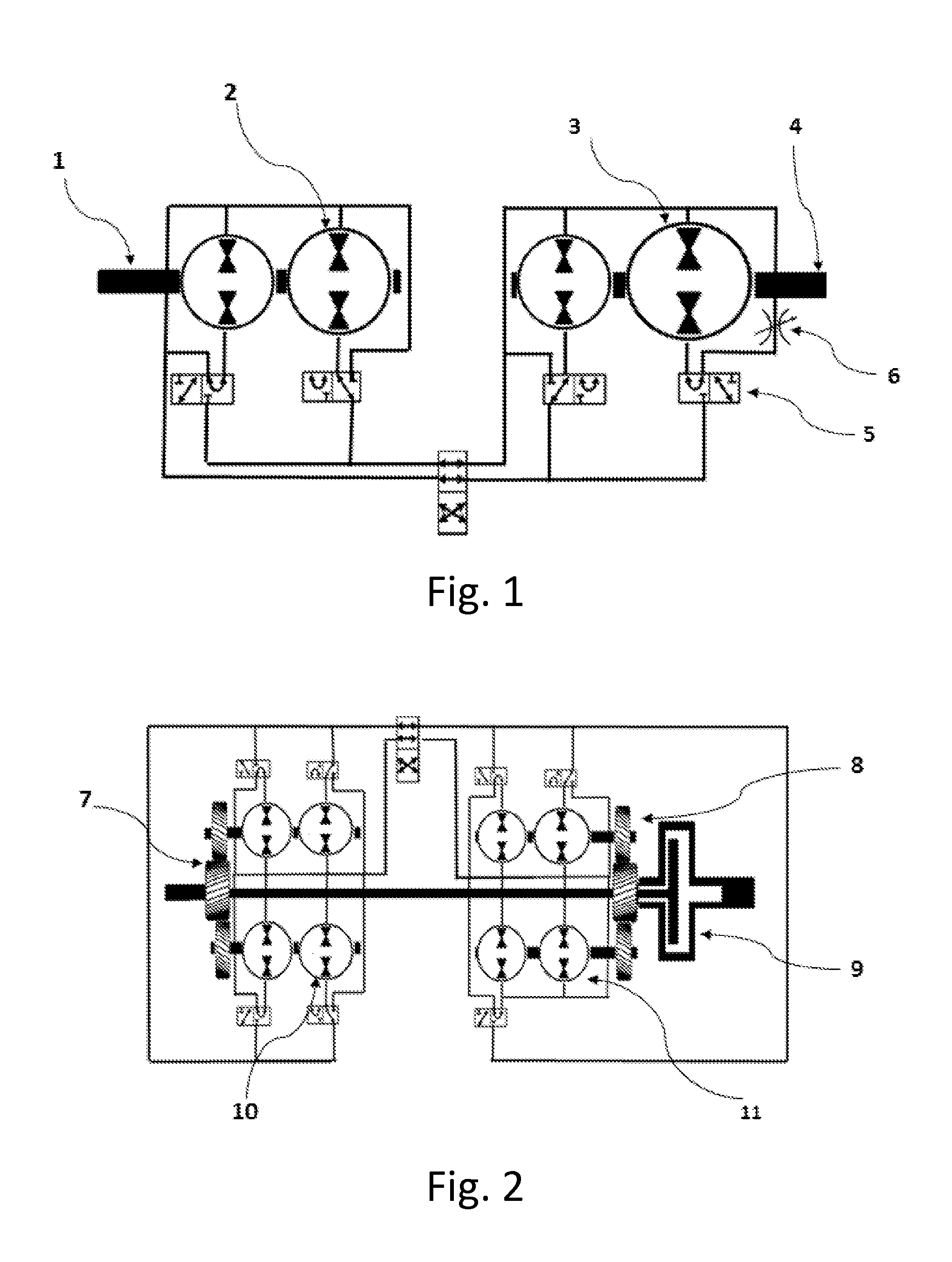
[0018]1 in FIG. 1 is the input shaft of a four pump / motor 2, 3 version of this transmission. Retarding or braking is accomplished by a valve 5 being positioned to cause the fluid in pump / motor 5 to recirculate. Closing flow restricting valve 6 will resist the turning motion of the output shaft 4 thereby applying a braking force to the vehicle.

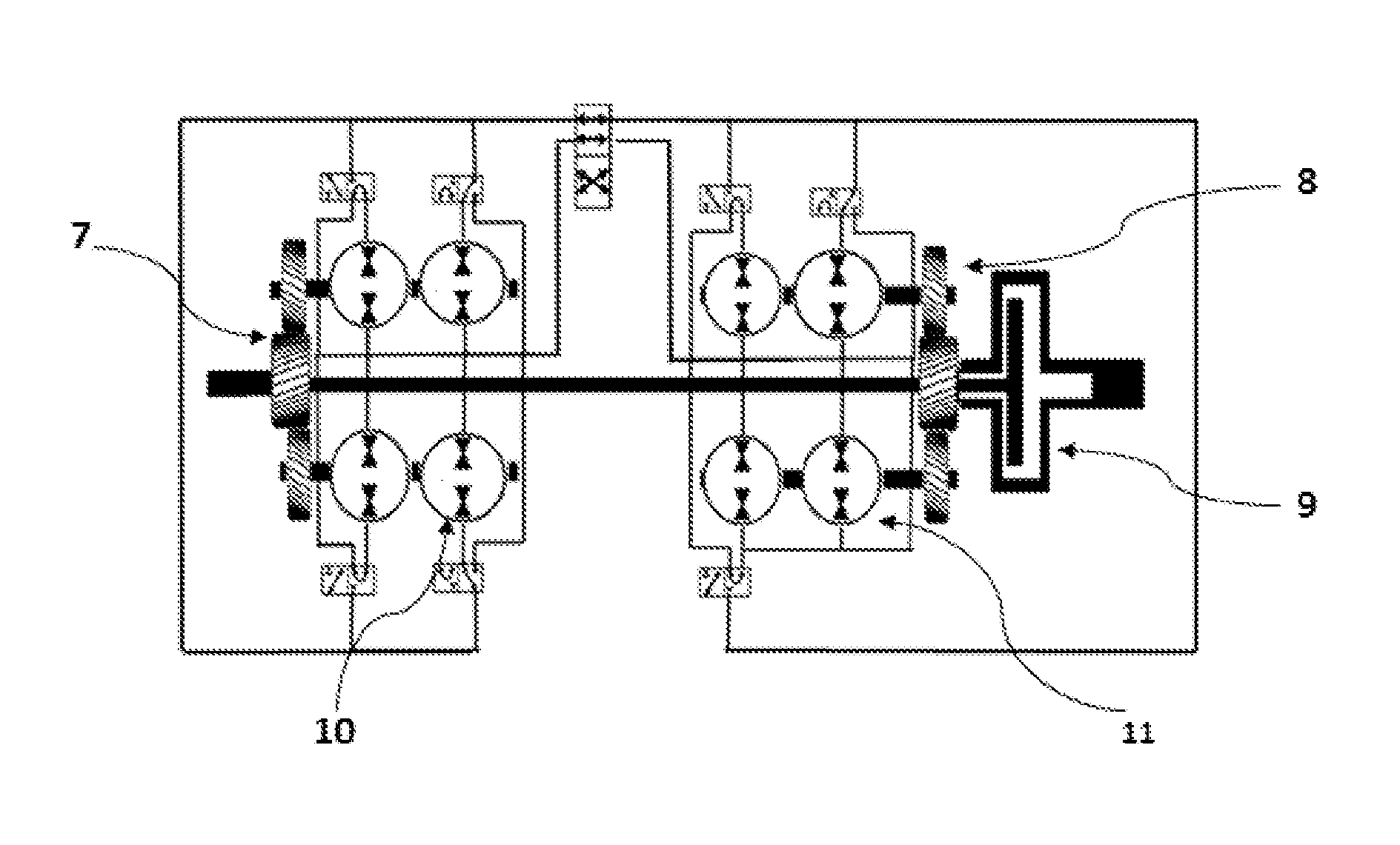
[0019]FIG. 2 is a schematic of an 8 pump / motor version of this transmission illustrating the speed-changing gears 7&8. 9 is a schematic representation of a selectable one-way clutch whose purpose is, when engaged, to provide a mechanical by-pass of the transmission during cruising and allow both input pump / motors 10 and output pump / motors 11 to contribute to the initial acceleration of the vehicle.

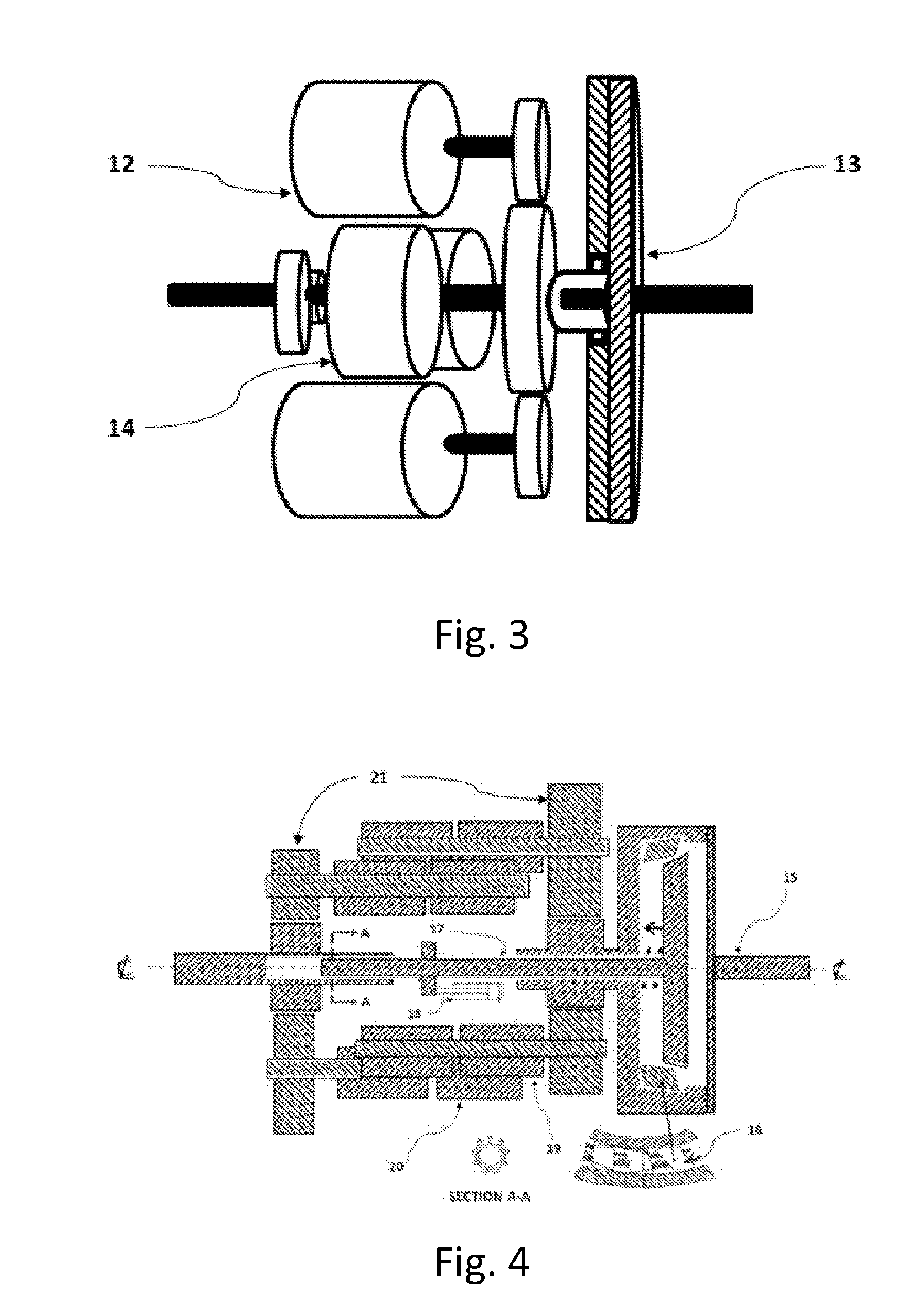
[0020]FIG. 3 illustrates how the clutch 13 allows the input pump / motors 14 to be “interleaved” with the output p...


PUM


Abstract

This invention consists of the addition of a novel clutch arrangement which facilitates speed changing gears on both the output and input of the transmission and provides for a compact packaging configuration for a plurality of hydraulic pump / motors. The use of a small accumulator without a valve and a related reservoir absorbs the pressure shocks from rapidly opening and closing the valves that that select or de-select the pump / motors. It is also disclosed that two adjacent pump / motors on the same shaft can be constructed such that they share an input or output port thereby reducing the size of the combination. The transmission can perform the retarder function by placing a flow retarding valve in the re-circulating path in one or more of the pump / motors.

Description

[0001]This application is a Continuation Application that claims the benefits of co-pending Non-provisional application Ser. No. 13 / 670,443 filed Nov. 06, 2012 and entitled “High Efficiency Hydro-mechanical Vehicle Transmission” and Provisional Application 61 / 897,753 filed Oct. 30, 2013 and entitled “Selectable One-way & Dog Clutch”TECHNICAL FIELD[0002]The present inventions relates a hydro-mechanical vehicle transmission based on fixed-displacement hydraulic pump / motors which also facilitates the implementation of hydraulic regenerative braking.BACKGROUND OF THE INVENTION[0003]Most present hydraulic transmission intended for vehicles are based on variable displacement hydraulic devices. None of them have been successfully applied to road vehicles due to problems associated with the variable displacement devices. These problems relate to efficiency, cost, form factor, noise and reliability.SUMMARY OF THE INVENTION[0004]This invention represents enhancements to that of application Se...

Claims


Application Information

Patent Timeline
Patent Type & Authority Applications(United States)
IPC IPC(8): F16H47/02F16H39/04
CPCF16H47/02F16H2047/025F16H39/04F16H61/4061
Inventor LLOYD, ROBERT HUGH FRANCIS
Owner LLOYD ROBERT HUGH FRANCIS
Why Eureka
Try Eureka