

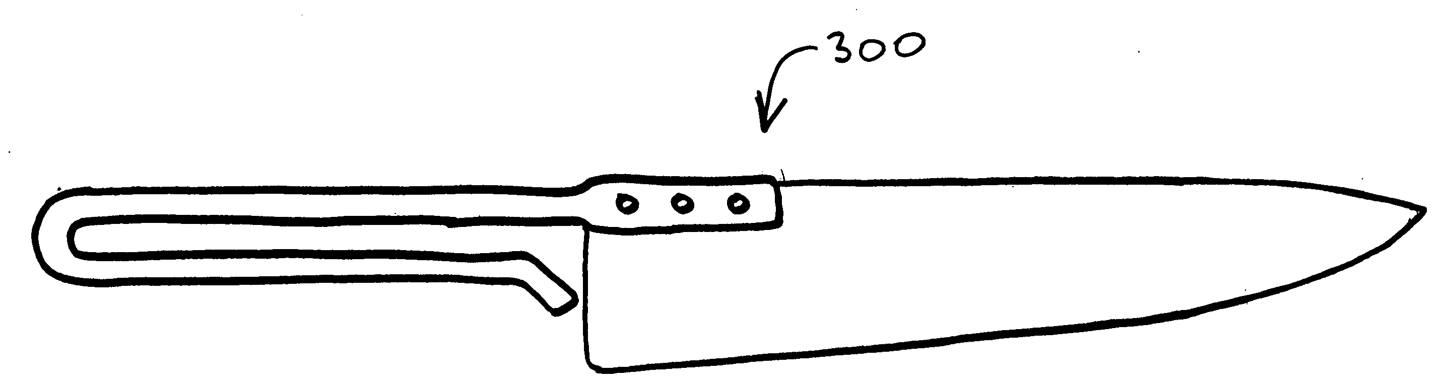
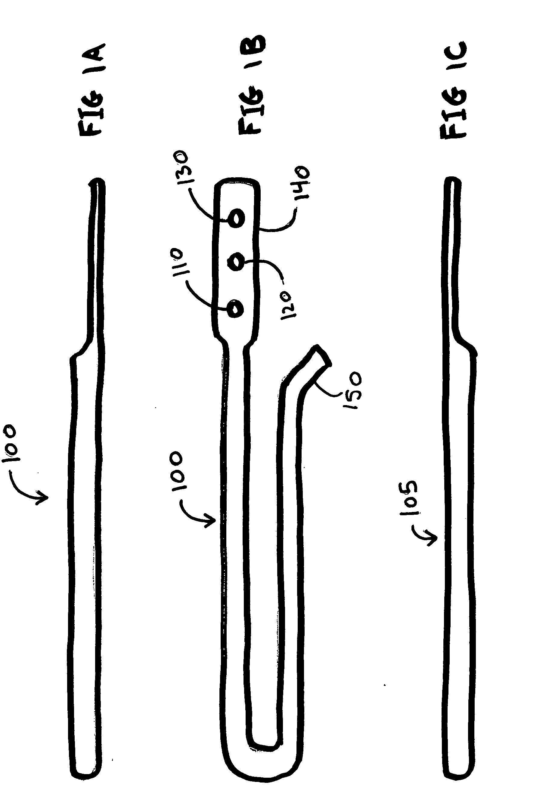
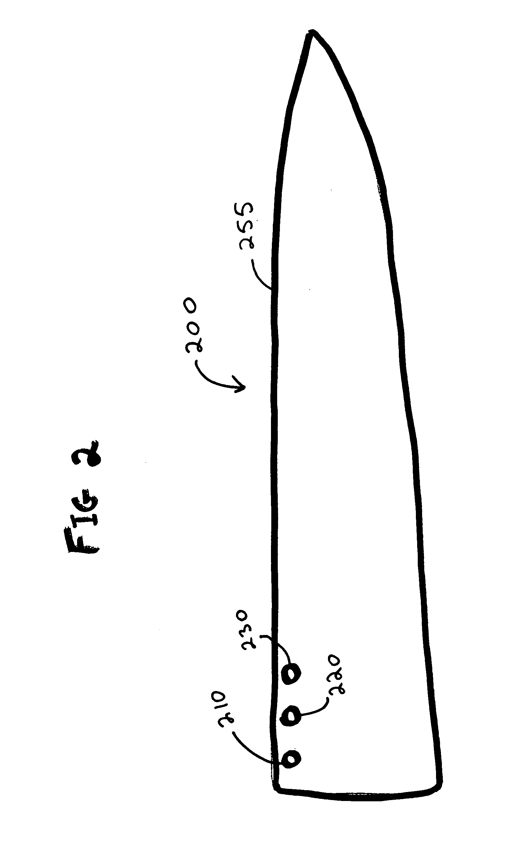
Knife, knife blade, knife rack and two U-shaped handle forms each attached at one end to the blade
a technology of knife blades and handles, applied in the field of knives, can solve the problems of difficult to keep clean knife holes in knife blocks, contaminated clean knives, and inconvenient putting knives in drawers, etc., and achieve the effects of convenient storage, increased gripping area, and increased safety and control
- Summary
- Abstract
- Description
- Claims
- Application Information
AI Technical Summary
Benefits of technology
Problems solved by technology
Method used
Image

Examples
Embodiment Construction
[0023]In exemplary embodiments of the present invention, each knife blade is manufactured without a tang. Depending on blade size, each knife blade has either two or three holes in the spine to accept rivets that hold the handles to the blade. Small blades (e.g. for a paring, steak, utility, or boning knife) have two rivet holes. Large blades (e.g. for a slicer, bread, or chef's knife) have three rivet holes. The heel of each blade is manufactured with an 8 millimeter radius on the spine and the ricasso.
[0024]One particular exemplary embodiment of the present invention will now be described. The description of this embodiment is for illustrative purposes only, and does not limit the various other embodiments that fall within the scope of the claimed invention. This embodiment pertains to a chef's knife, and a person of ordinary skill will understand that the same basic principles apply, for example, to a paring knife, a boning knife, a utility knife, and various other types of knive...
PUM
 Abstract
Description
Claims
Application Information