Self Actuating Underreamer

a self-actuating, under-reamer technology, applied in earth drilling and mining, drill bits, drills, etc., can solve the problems of compromising the integrity of the hole, affecting the accuracy of the drilling, and expensive removal of the under-reamer

Inactive Publication Date: 2008-10-16
MINSHULL RONALD GEORGE
View PDF10 Cites 11 Cited by
  • Summary
  • Abstract
  • Description
  • Claims
  • Application Information

AI Technical Summary

Benefits of technology

[0008]Once the obstruction has been cleared, the operator causes the casing to advance relative to the underreamer such that the casing forces the pivot arms to retract into the casing and into the body of the underreamer into their retracted position. If desired, the underreamer can be completely removed by withdrawing it entirely through the inside of the casing.

Problems solved by technology

When they jam, the underreamers are expensive to remove, with the removal process sometimes requiring the withdrawal of the casing and the associated risk of compromising the integrity of the hole.

Method used


Image

  • Self Actuating Underreamer
  • Self Actuating Underreamer
  • Self Actuating Underreamer

Examples


Embodiment Construction

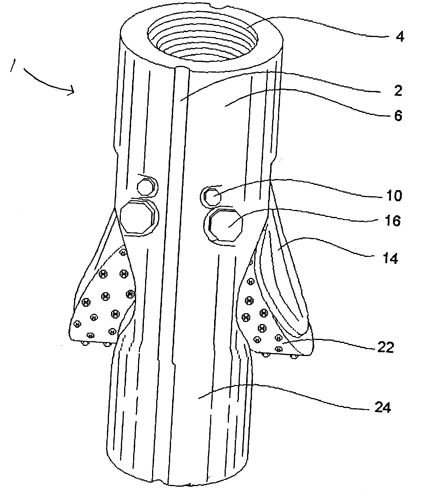
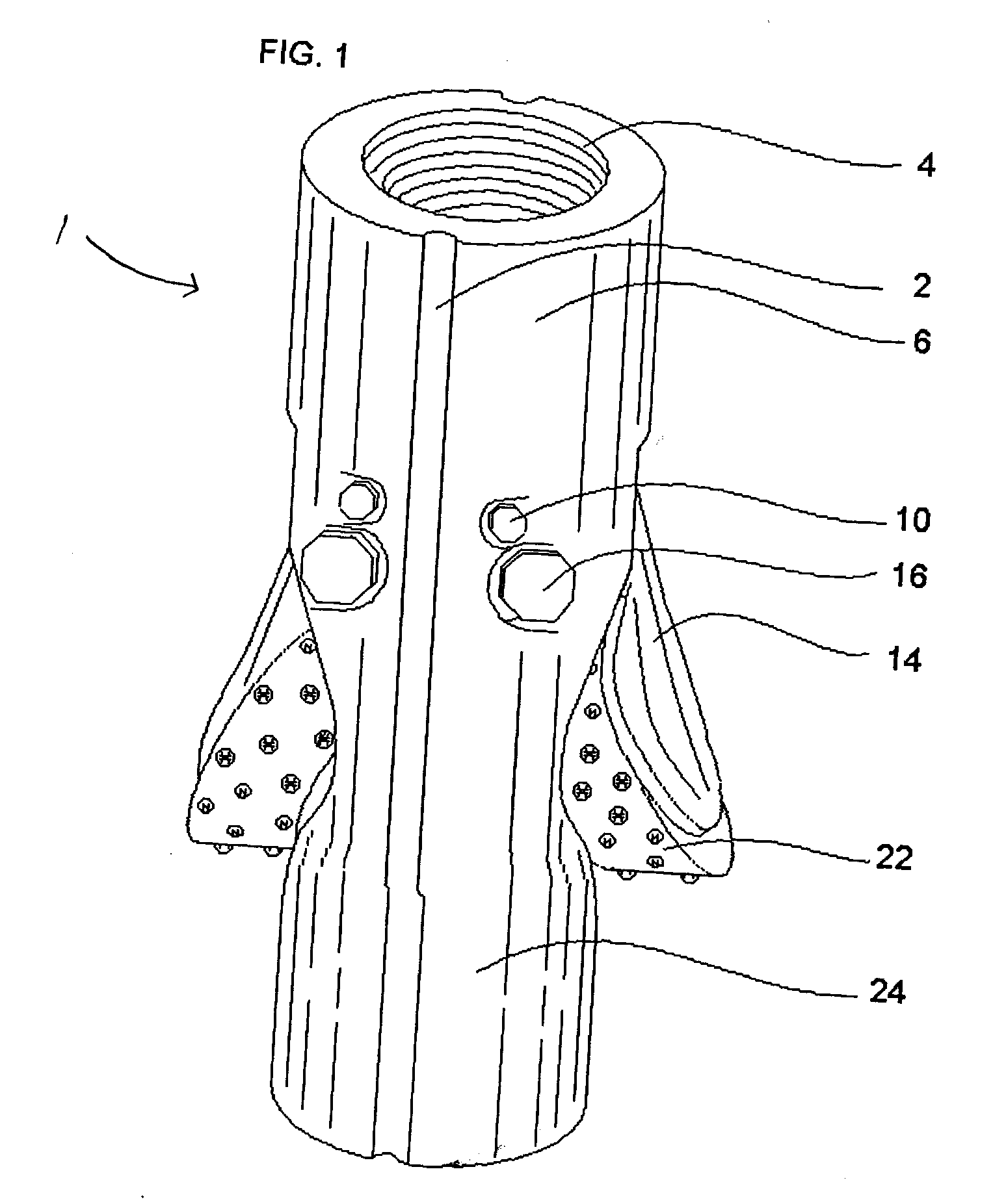
[0032]Referring to FIG. 1, the underreamer 1 according to the invention comprises an upper stabilizer body portion 6 and a lower stabilizer body portion 24.

[0033]Cutters comprise generally cone arms 14 and roller cutters 22. A pair of cone arms 14 are pivotably retained by a pair of swivel pins 16. Stop pins 10 are positioned to limit the outward pivotal displacement of the cone arms 14. Roller cutters 22 are mounted at the ends of cone arms 14. Blade cutters may be substituted for roller cutters 22. The upper end of the upper stabilizer body potion 6 is threaded as at 4 for securing the underreamer to the drill stem (not shown).

[0034]The outside of the upper body portion 6 is provided with an upper stabilizer channel 2 for return fluid circulation and cutting removal.

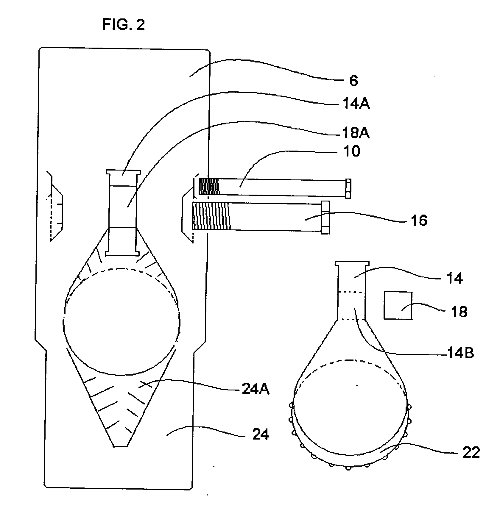
[0035]Referring to FIG. 2, the body of the underreamer includes, for each roller cone, a cavity 24A for receiving the roller cutter 22 and a recess 14A for receiving cone arm 14.

[0036]A cylindrical linking guide elemen...


PUM


Abstract

An underreamer for well drilling comprises pivotally extendible roller cutters that extend slightly beyond the diameter of the pilot drill bit but are retained in their retracted position by the casing. Upon encountering an obstruction, the underreamer is pushed out of the casing, allowing the outer edges of the cutters to contact the obstruction. Continued downward pressure of the drill stem causes the roller arms to pivot outward to a fully extended position in which the cutters enlarge the hole to a diameter larger than the casing by rotation of the drilling stem. The advance of the casing relative to the underreamer forces the cutters to retract into the casing.

Description

TECHNICAL FIELD OF THE INVENTION[0001]This invention relates to underreamers used in simultaneous drilling and casing operations. More generally, this invention relates to means for enlarging a borehole created by rotary apparatus.BACKGROUND OF THE INVENTION[0002]In simultaneous drilling and casing operations, a section of casing follows the drill bit into the borehole. Underreamers located upstream of the drill bit and downstream of the end of the casing are used to enlarge the hole when necessary, such as when an obstruction in the formation is encountered. Such underreamers typically rely on springs or hydraulic pressure to actuate the roller cutters from a retracted, inoperative position to an extended, operating position. When they jam, the underreamers are expensive to remove, with the removal process sometimes requiring the withdrawal of the casing and the associated risk of compromising the integrity of the hole.[0003]Examples of a trailing underreamer used in conjunction wi...

Claims


Application Information

Patent Timeline
Patent Type & Authority Applications(United States)
IPC IPC(8): E21B10/32E21B7/00
CPCE21B10/34
Inventor MINSHULL, RONALD GEORGE
Owner MINSHULL RONALD GEORGE
Why Eureka
Try Eureka