Determining a Geolocation Solution of an Emitter on Earth Based on Weighted Least-Squares Estimation

a geolocation solution and weighted least-squares technology, applied in direction finders, instruments, measurement devices, etc., can solve problems such as inability to meet conditions in practice, not being able to obtain two measurements at the same time, and not being able to accurately estimate the location of the emitter

Active Publication Date: 2008-10-16
GLOWLINK COMMUNICATIONS TECHNOLOGY INC
View PDF15 Cites 10 Cited by
  • Summary
  • Abstract
  • Description
  • Claims
  • Application Information

AI Technical Summary

Benefits of technology

[0013]In one embodiment, the weights for the errors in the TDOA and FDOA measurements depend on the emitter position. An estimate of the emitter position is made, for example, by using a TDOA-FDOA s

Problems solved by technology

In practice, this is often not the case or not even possible.
For example, the technical limitations of the equipment, including the limitations in the aperture of th

Method used


Image

  • Determining a Geolocation Solution of an Emitter on Earth Based on Weighted Least-Squares Estimation
  • Determining a Geolocation Solution of an Emitter on Earth Based on Weighted Least-Squares Estimation
  • Determining a Geolocation Solution of an Emitter on Earth Based on Weighted Least-Squares Estimation

Examples


Embodiment Construction

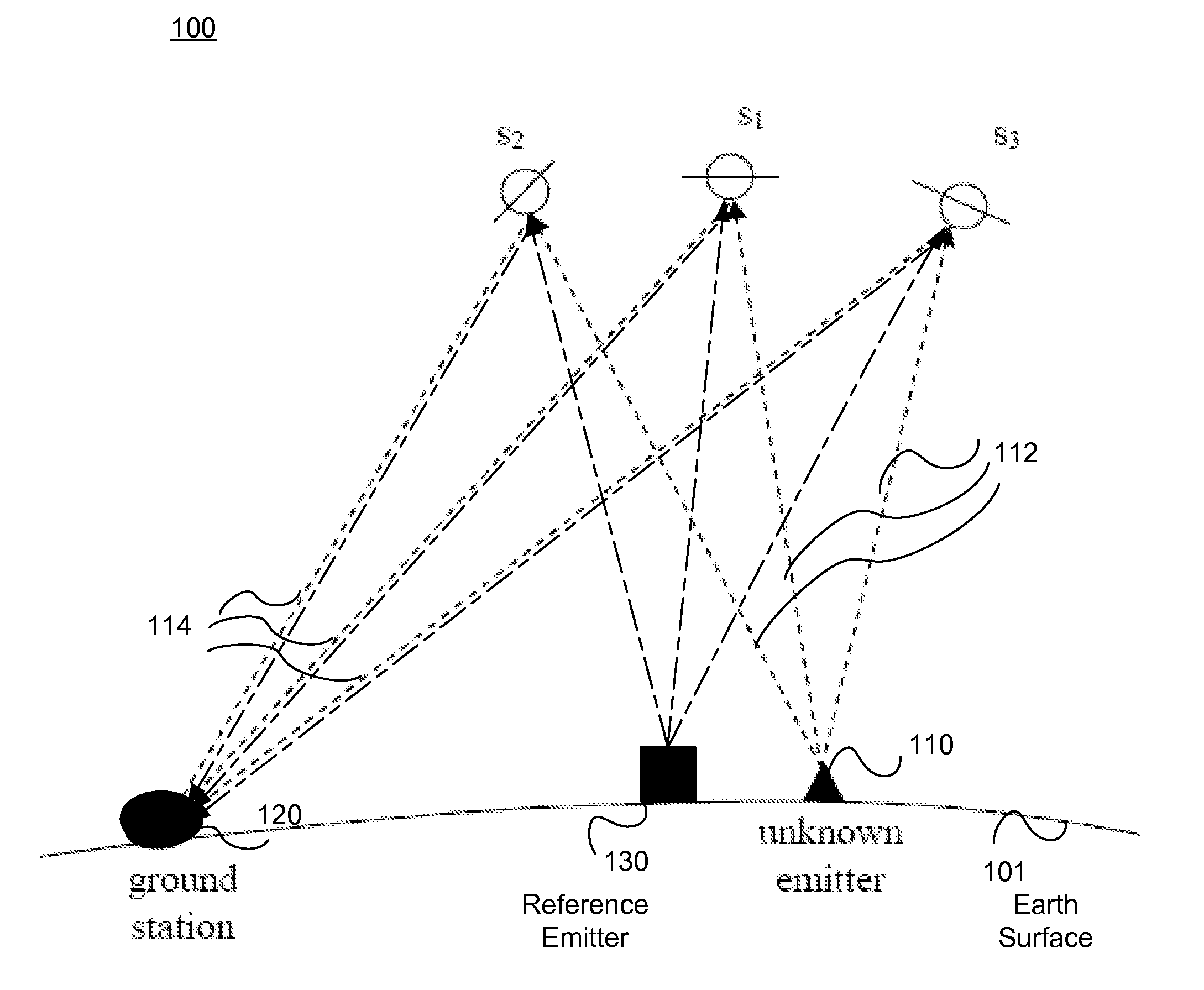
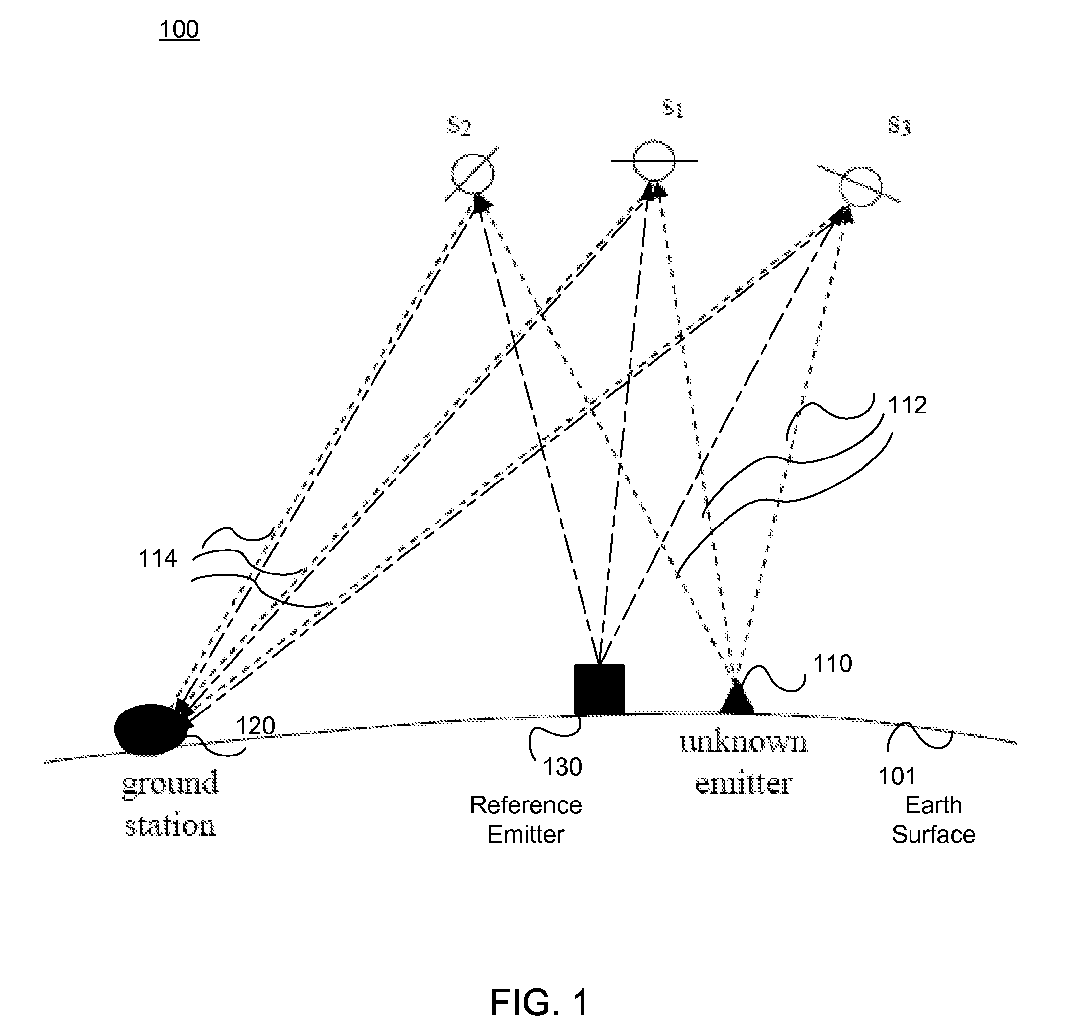
[0022]FIG. 1 illustrates the geolocation scenario 100 where an emitter 110 with an unknown location emits signals 112 that are received at an observer, referred to herein as a ground station 120, through three different satellites. As described above, the satellites s1, s2, and s3 have non-zero velocities with respect to the earth. The unknown emitter 110 sends out signal 112 and it is received by the satellites s1, s2, and s3. The satellites s1, s2, and s3 relay the signal 114 to a ground station 120.

[0023]The ground station 120 determines the time-difference of arrival (TDOA), denoted as d21, between the signal 112 from the emitter 110 through the primary satellite s1 to the ground station 120 and the signal 112 from the emitter 110 through another satellite s2 to the ground station 120. Similarly, the TDOA of the signal 112 from the emitter 110 through the first satellite s1 to the ground station 120 and the signal 112 from the emitter 110 through a third satellite s3 to the grou...


PUM


Abstract

Embodiments provide systems and methods for determining the geolocation of an emitter on earth based on weighted least-squares estimation based on two TDOA and two FDOA measurements, none of which need to be acquired at the same time. The four TDOA and FDOA measurements and the errors in each of the measurements are determined. Weights for the errors in the TDOA and FDOA measurements are determined, and the weights are applied in a weighted errors function. The weights account for the errors in the measurements and the errors in the satellite positions and velocities, and are dependent on the localization geometry. The weighted errors function is minimized to determine the location estimate of the unknown emitter.

Description

CROSS-REFERENCE TO RELATED APPLICATION(S)[0001]This application is related to U.S. patent application Ser. No. ______, titled “Determining A Geolocation Solution Of An Emitter On Earth Using Satellite Signals”, filed herewith (with attorney docket no. 25760-12471), which is hereby incorporated by reference in its entirety.BACKGROUND OF THE INVENTION[0002]1. Field of the Invention[0003]This invention pertains to determining a geolocation for unknown emitters based on measurements of satellite signals.[0004]2. Description of the Related Art[0005]FIG. 1 shows a geolocation scenario 100 where an emitter 110 on the earth's surface 101 can be located using three satellites s1, s2, and s3. The satellites s1, s2, and s3 have non-zero velocities with respect to the earth. The unknown emitter 110 sends out signal 112 and it is received by the satellites s1, s2, and s3. The satellites s1, s2, and s3 relay the signal 114 to a ground station 120 or other observation point.[0006]The ground statio...

Claims


Application Information

Patent Timeline
IPC IPC(8): G01S1/24G01S19/11
CPCG01S5/0257G01S5/12G01S19/426
Inventor HO, DOMINIC K. C.CHU, JEFFREY C.DOWNEY, MICHAEL L.
Owner GLOWLINK COMMUNICATIONS TECHNOLOGY INC
Why Eureka
Try Eureka