Multiple Channel Communication

a multi-channel communication and multi-channel technology, applied in the field of multi-channel communication, can solve the problem that the most time-varying components of noise tend to result from interferen

Inactive Publication Date: 2008-10-16
KONINKLJIJKE PHILIPS NV
View PDF4 Cites 9 Cited by
  • Summary
  • Abstract
  • Description
  • Claims
  • Application Information

AI Technical Summary

Benefits of technology

[0018]means for calculating powers Pi to be allocated to the respective channels of the system by maximisin

Problems solved by technology

However, most time varying components of

Method used


Image

  • Multiple Channel Communication
  • Multiple Channel Communication
  • Multiple Channel Communication

Examples


Embodiment Construction

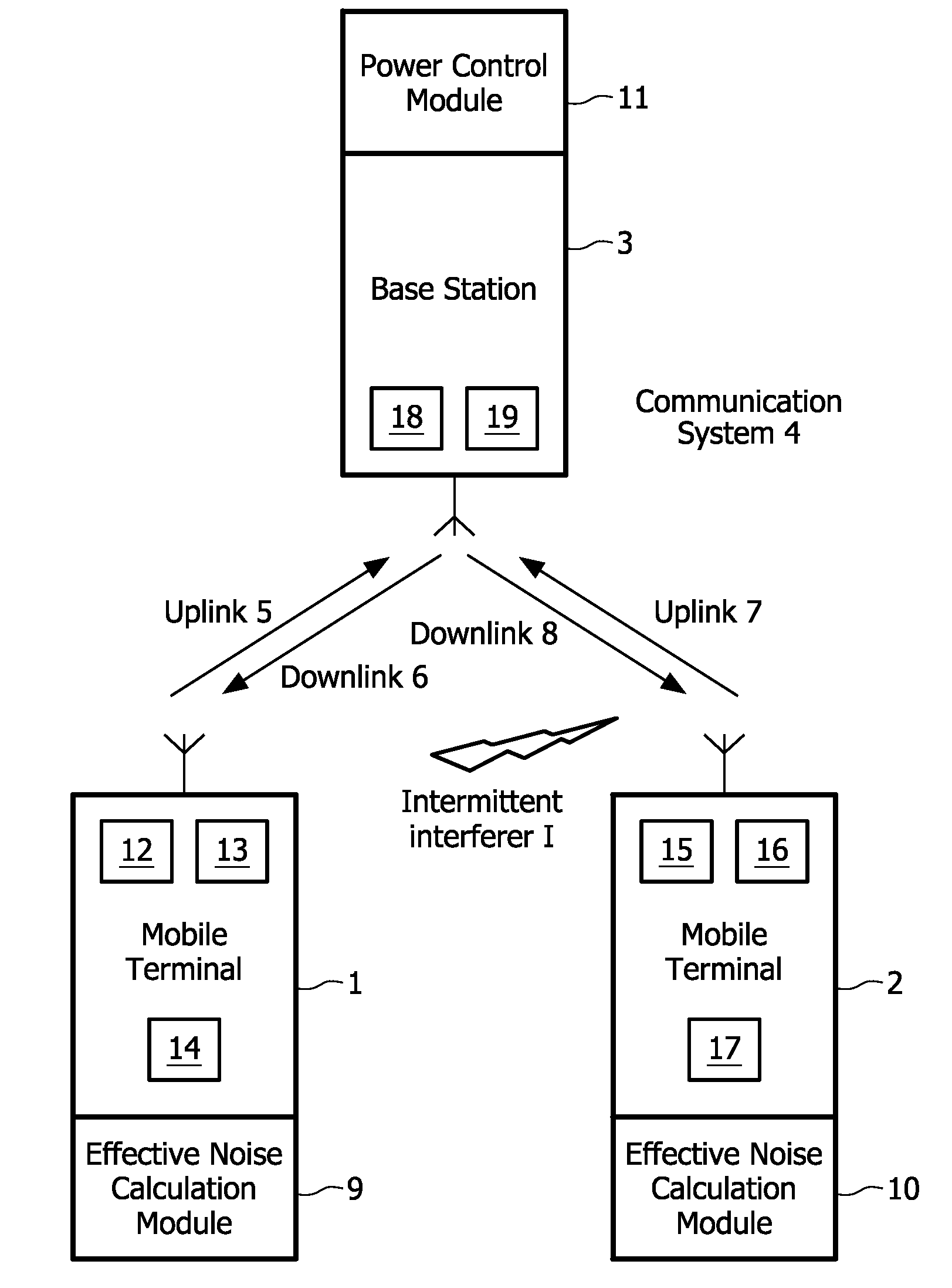
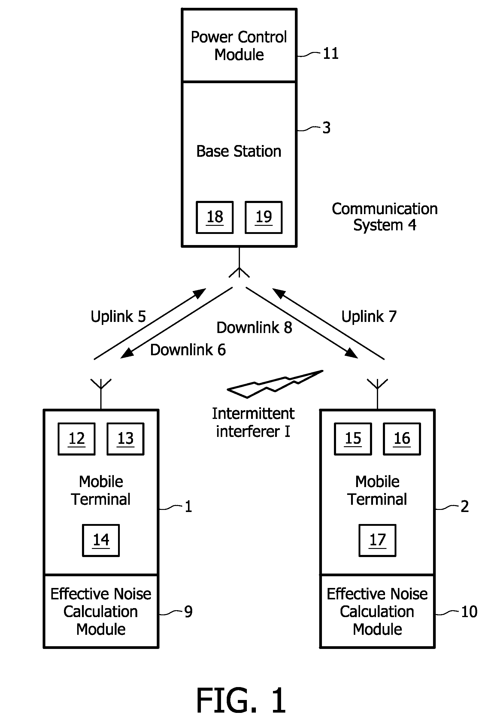
[0028]Referring to FIG. 1, two mobile terminals 1, 2 are able to communicate with a base station 3 of a communication system 4. A first of the mobile terminals 1 has a transmitter 12 for transmitting signals to the base station 3 over a first uplink 5, a receiver 13 for receiving signals from the base station 3 over a first downlink 6, and may have a processor 14 for calculating power such as estimating an initial power level or calculating powers to be allocated to communication channels. Similarly, a second of the mobile terminals 2 has a transmitter 15 for transmitting signals to the base station 3 over a second uplink 7, a receiver 16 for receiving signals from the base station 3 over a second downlink 8, and may have a processor 17 for calculating power levels such as estimating an initial power level or calculating powers to be allocated to communication channels. The mobile terminals 1, 2 each have an effective noise calculation module 9, 10 for calculating effective noise Ne...


PUM


Abstract

A communication device (1) for communicating in a multiple channel communication system comprises means (9) for calculating an effective noise level of one of the channels of the system by applying an expectation operator to an estimated noise level affecting the channel based on time varying characteristics of the estimated noise level. The calculation of the effective noise level may also be based on an estimated path loss. The calculation of the effective noise level may also be based on an initial power level allocated to the respective channel. The effective noise level calculated for each channel may be employed in calculating power levels to be allocated to the respective channels.

Description

TECHNICAL FIELD[0001]This invention relates to a communication device for operation in a multiple channel communication system and to a method of operating the same. A particular, but not exclusive, application of the invention is the calculation of an effective noise level for use in allocating power to the multiple communication channels of the system.BACKGROUND ART[0002]Communication systems invariably have only limited bandwidth. Communication systems that use multiple channels share this bandwidth between the channels of the system and there are numerous schemes for deciding how the bandwidth should be shared. This invention concerns schemes that vary the power or such like with which signals are transmitted over different channels according to the quality of signals received over the different channels in order to optimise the overall performance of the system, e.g. by maximising say the overall communication capacity of the communication system.[0003]For example, it is known ...

Claims


Application Information

Patent Timeline
IPC IPC(8): H04Q7/00H04W52/14H04W52/22H04W52/24H04W52/50
CPCH04W52/143H04W52/225H04B17/345H04W52/247H04W52/50H04W52/243H04W88/08
Inventor MOULSLEY, TIMOTHY J.HUNT, BERNARDROBERTS, DAVID K.BAKER, MATTHEW P.J.TOSATO, FILIPPO
Owner KONINKLJIJKE PHILIPS NV
Why Eureka
Try Eureka