Ear speaker device

a speaker device and earphone technology, applied in the field of ear speakers, can solve the problems of deteriorating sound quality and unnaturalness, and achieve the effect of high quality, sufficient low-pitched sound and high quality

Inactive Publication Date: 2008-10-16
SONY CORP
View PDF14 Cites 20 Cited by
  • Summary
  • Abstract
  • Description
  • Claims
  • Application Information

AI Technical Summary

Benefits of technology

The present invention provides an ear speaker device that can provide natural sound image localization and make the listener listen to a reproduced sound of high quality. The device includes an electroacoustic transducer with a housing mounted on the head of the listener, a speaker unit positioned away from the entrance of the external acoustic meatus, and a tubular duct that emits a sound generated by the housing in the inner space of the duct. The device can provide unnatural sound quality when using a closed type, but the present invention solves this problem by providing an open type ear speaker device that allows for natural sound image localization and stable listening to the sound. The device can also be rotated to improve sound quality and stability.

Problems solved by technology

Meanwhile, in thus configured headphone device, even if the speaker unit is positioned at a location somewhat distant from the entrance of the external acoustic meatus (ear hole) and closer to a parietal region, in case a reproduced sound etc. of contents to be listened to by the listener is emitted from a sound source of the stereo source, a sound image is localized in the head of the listener, and there is raised a problem that the unnaturalness is not removed.
However, since the speaker unit is isolated from the ear hole, the sound quality becomes deteriorated with insufficient low frequencies when nothing further than changing the closed type to the open type is carried out, and there has been a problem that the above request is not fulfilled.

Method used


Image

  • Ear speaker device
  • Ear speaker device
  • Ear speaker device

Examples


first embodiment

(1) First Embodiment

(1-1) Configuration of Ear Speaker Device

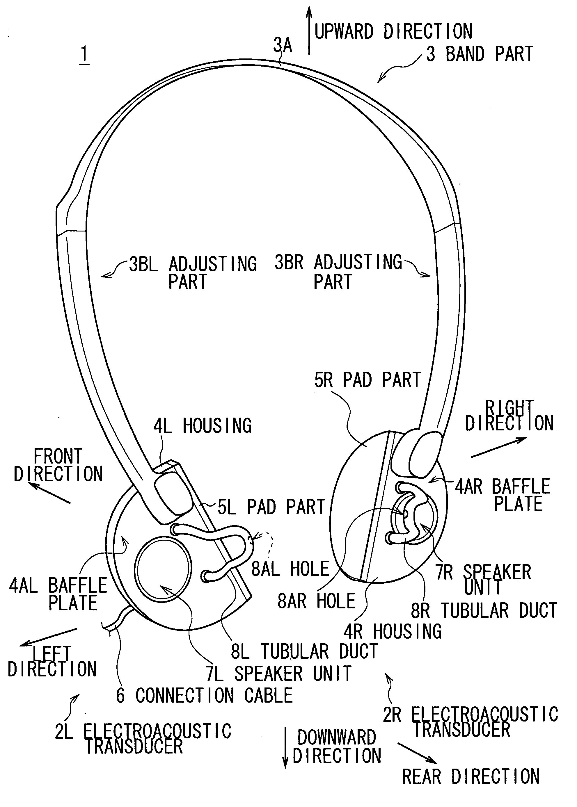
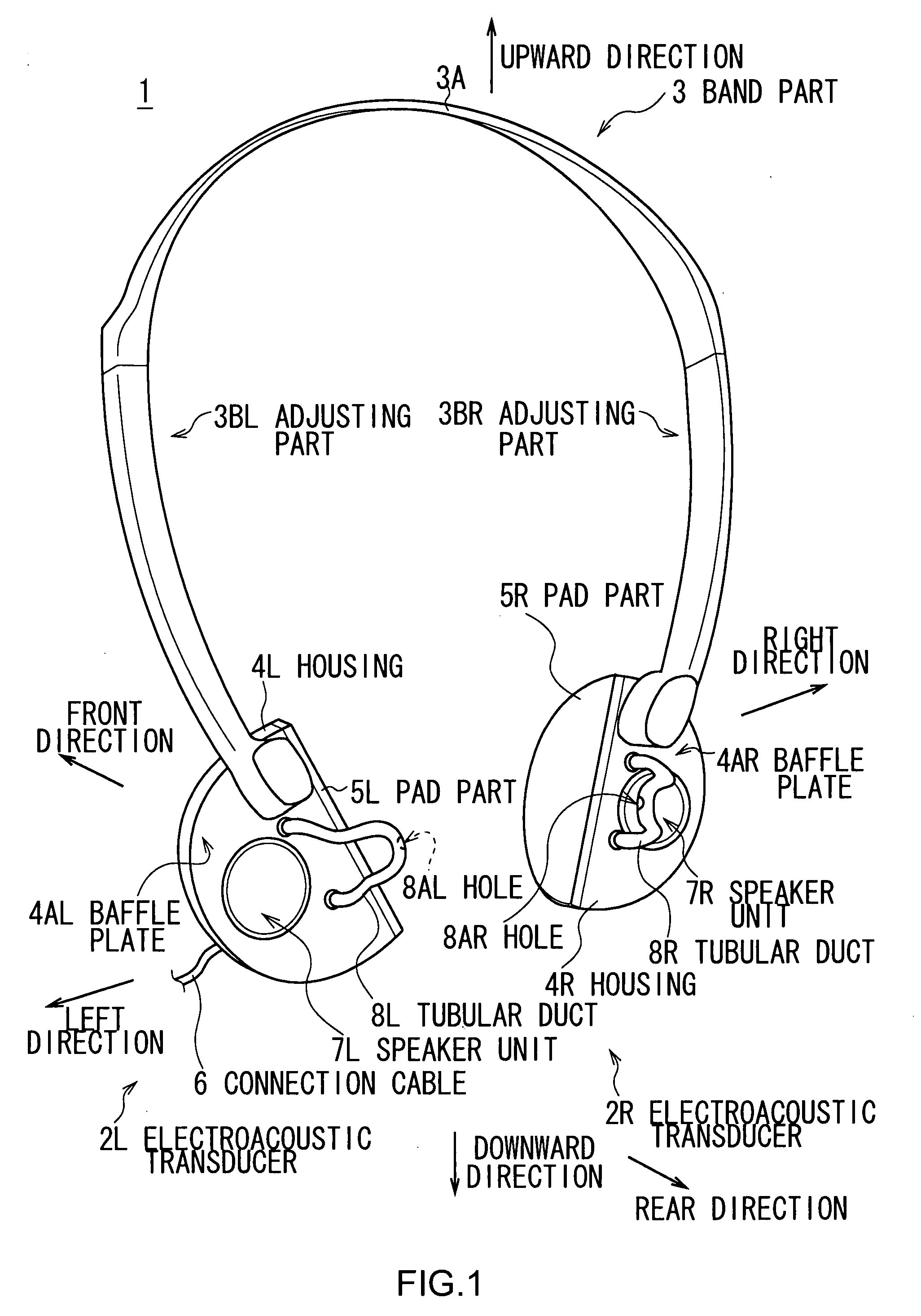
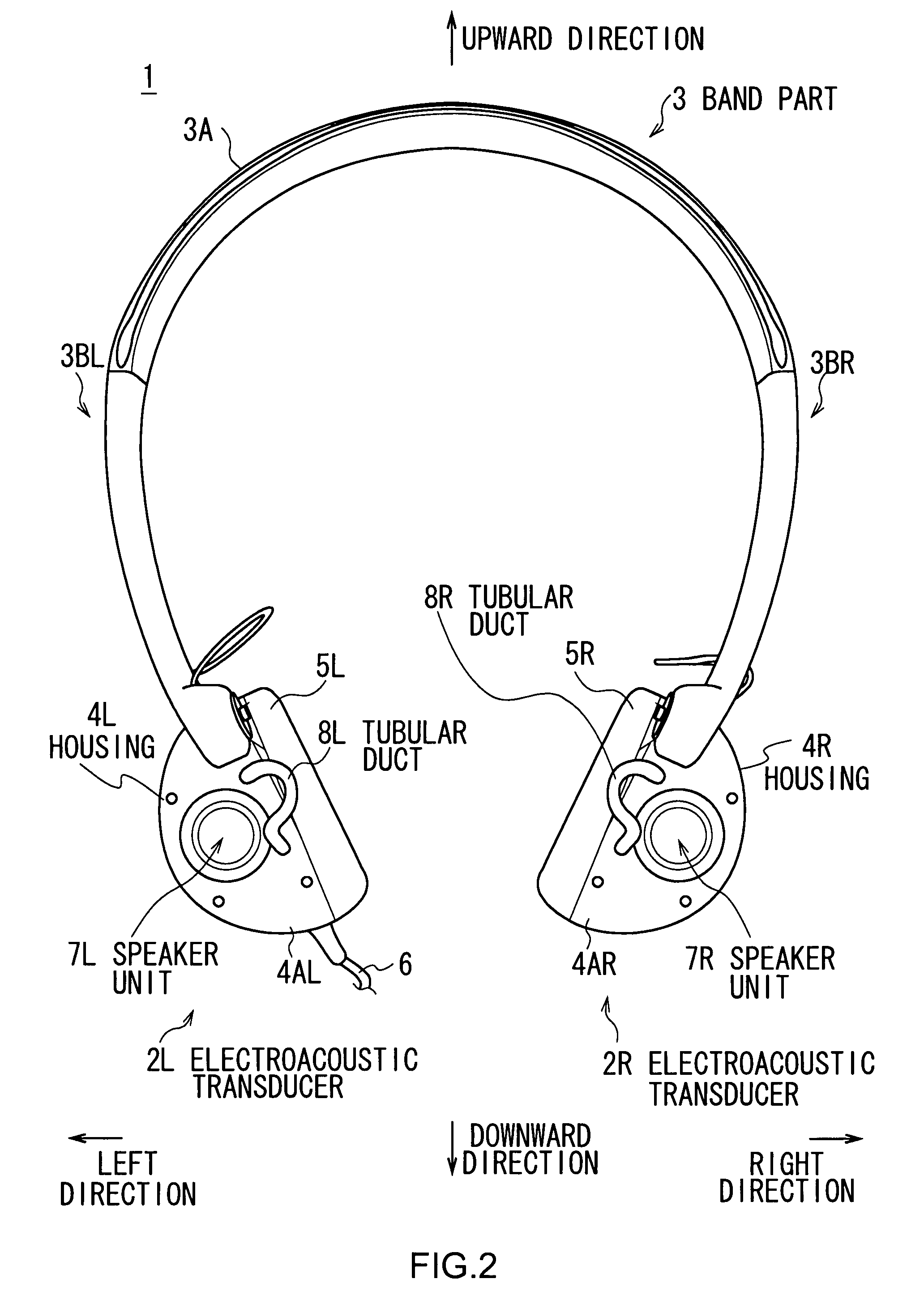
[0105]With respect to FIGS. 1, 2, and 3, the numerical number 1 refers to an entire ear speaker device according to the first embodiment. The ear speaker device is configured so as to convert an audio signal generated by reproduction processing and the like of a portable compact disc (CD) player and a digital music player (DMP) to a reproduced sound, and make a listener capable of listening to the reproduced sound.

[0106]Unlike a box-shaped speaker device generally used, the ear speaker device 1 is premised to be mounted on the head of the listener as similar to a headphone device. The ear speaker device 1 is configured with electroacoustic transducers 2L and 2R that convert the audio signal to the reproduced sound, and a band part 3 for mounting and fixing the electroacoustic transducers 2L and 2R on the head of the listener, according to a rough classification.

[0107]The electroacoustic transducers 2L and 2R are mainly con...

second embodiment

(2) Second Embodiment

(2-1) Configuration of Ear Speaker Device

[0196]In FIGS. 22 and 23 in which a corresponding part is attached with the same numerical number as found in FIG. 1, the numerical number 200 shows the entire ear speaker device according to the second embodiment. The ear speaker device 200 converts the audio signal generated by reproduction processing, and so on of a portable CD player and a DMP to the reproduced sound, and makes the listener capable of listening to the reproduced sound.

[0197]The ear speaker device 200 is also premised to be mounted on the head of the listener as similar to a normal headphone device unlike a general box-type speaker device. The ear speaker device 200 is configured with electroacoustic transducers 202L and 202R that convert the audio signal to the reproduced sound and the band part 3 that mounts and fixes the electroacoustic transducers 202L and 202R on the head of the listener, as a rough classification.

[0198]The electroacoustic transdu...

third embodiment

(3-1) Third Embodiment

[0267]As shown in FIGS. 1 to 5, when the ear speaker device 1 of the first embodiment is mounted on the head 100 of the listener, the tubular ducts 8L and 8R are extended to the vicinity of the entrances 102L and 102R (not shown) of the external acoustic meatus respectively, and ducts of various figurations may be employed instead of the tubular ducts 8L and 8R.

[0268]As shown in FIGS. 39 to 41 corresponding to FIGS. 1, 4 and 5, the ear speaker device 20 corresponding to the ear speaker device 1 has electroacoustic transducers 22L and 22R instead of the electroacoustic transducers 2L and 2R.

[0269]The electroacoustic transducers 22L and 22R have tubular ducts 28L and 28R instead of the tubular ducts 8L and 8R. Similar to the tubular ducts 8L and 8R, the tubular ducts 28L and 28R are formed by curving a hollow member into a substantial U-shape respectively on sides. On the other hand, the length of parts of the tubular ducts 28L and 28R protruding from the baffle ...


PUM


Abstract

An ear speaker device includes an electroacoustic transducer including a housing mounted at a predetermined position of listener's head, a speaker unit mounted on one surface in the housing, and positioned away from an entrance of the listener's external acoustic meatus for a predetermined distance when the housing is mounted on the listener's head, and a tubular duct extended so as to allow a sound generated by the housing in the inner space thereof to reach the vicinity of the entrance of the listener's external acoustic meatus, and a hole for emitting sound of the duct is oriented to the opposite direction with respect to the entrance of the external acoustic meatus; and a mounting part used for mounting the electroacoustic transducer on the listener's head in a manner that the predetermined distance is provided between the speaker unit and the entrance of the listener's external acoustic meatus.

Description

CROSS REFERENCES TO RELATED APPLICATIONS[0001]The present invention contains subject matter related to Japanese Patent Applications JP2006-328604, JP2006-328606, JP2006-328608 filed in the Japanese Patent Office on Dec. 5, 2007, and Japanese Patent Application JP2006-332216 filed in the Japanese Patent Office on Dec. 8, 2007, the entire contents of which being incorporated herein by reference.BACKGROUND OF THE INVENTION[0002]1. Field of the Invention[0003]This invention relates to an ear speaker device, and is desirably applied to a head-mounted wearable speaker device.[0004]2. Description of the Related Art[0005]As a headphone device being one example of a head-mounted wearable speaker device, there are widely diffused devices which are mounted to the head of the listener, and convert an audio signal representing a reproduced sound etc. of a compact disc (CD) to a sound (referred to as reproduced sound, hereinafter), and make the listener listen to the reproduced sound.[0006]In the...

Claims


Application Information

Patent Timeline
Patent Type & Authority Applications(United States)
IPC IPC(8): H04R25/00
CPCH04R1/1066H04R1/26H04R1/2819H04R1/2865H04R2460/13H04R5/033H04R5/0335H04R2201/107H04R1/345
Inventor YAMAGISHI, MAKOTOSEKI, HIDEKIHIYAMA, NORIYUKIYAMAGUCHI, YUKIMASAHARA, TAKESHI
Owner SONY CORP
Why Eureka
Try Eureka