Roller drive control method of fixing apparatus and fixing apparatus

a technology of fixing apparatus and drive control method, which is applied in the direction of electrographic process apparatus, instruments, optics, etc., can solve the problems of affecting the control, affecting the control, and affecting the control, so as to facilitate the vibration of the separation claw

Inactive Publication Date: 2008-10-16
SHARP KK
View PDF2 Cites 4 Cited by
  • Summary
  • Abstract
  • Description
  • Claims
  • Application Information

AI Technical Summary

Benefits of technology

[0036]Furthermore, when a face of the separation claw opposing the surface of the fixing roller is a convex shape, only a central area of the face of the separation claws opposing the surface of the fixing rollers comes in contact with the fixing rollers, thus facilitating vibration of the separation claws.
[0037]Further still, when a gap between the surface of the fixing roller and a leading edge of the separation claw is narrower than a thickness of the recording paper, it becomes difficult for the recording paper to enter the gap between the surface of the fixing roller and the leading edge of the separation claw and enables jams and the like caused by the recording paper entering the gap to be prevented.
[0038]Furthermore, when a portion of a convex face of the separation claw contacts the surface of the fixing roller, vibration of the separation claws is facilitated as mentioned above.

Problems solved by technology

However, not all the toner is fused and fixedly attached onto the recording paper by the fixing process, and a small amount of toner transfers and adheres to the fixing roller side since the fixing rollers have a high surface temperature.
Furthermore, when a lump of toner that has adhered to and accumulated on the separation claw becomes large, it may drop and adhere to the surface of the fixing rollers.
The large lump of toner on the surface of the fixing rollers cannot be fully removed by the cleaning apparatus at one time and may get stuck with peripheral components such as temperature detecting thermistors provided around the surface of the fixing rollers, which may be a cause of damage to the peripheral components.
However, when using a heater to heat the separation claw in the manner of JP 2003-156967A, it is necessary to provide a sensor to detect the temperature of the separation claw and to control the temperature of the separation claw, which makes it impossible to avoid increasing the number of components and complicating the control thereof.
Furthermore, along with increasing speeds in image forming apparatuses there have been increasing numbers of sheets of recording paper to be processed by the fixing apparatuses, which increases the amount of heat of the fixing rollers, and since the power consumption involved for that has increased close to the rating for commercial AC power, it is undesirable to invite further increases in the amount of heat for heating the separation claw.

Method used


Image

  • Roller drive control method of fixing apparatus and fixing apparatus
  • Roller drive control method of fixing apparatus and fixing apparatus
  • Roller drive control method of fixing apparatus and fixing apparatus

Examples


Embodiment Construction

[0046]Hereinafter, an embodiment of the present invention is described in detail with reference to the accompanying drawings.

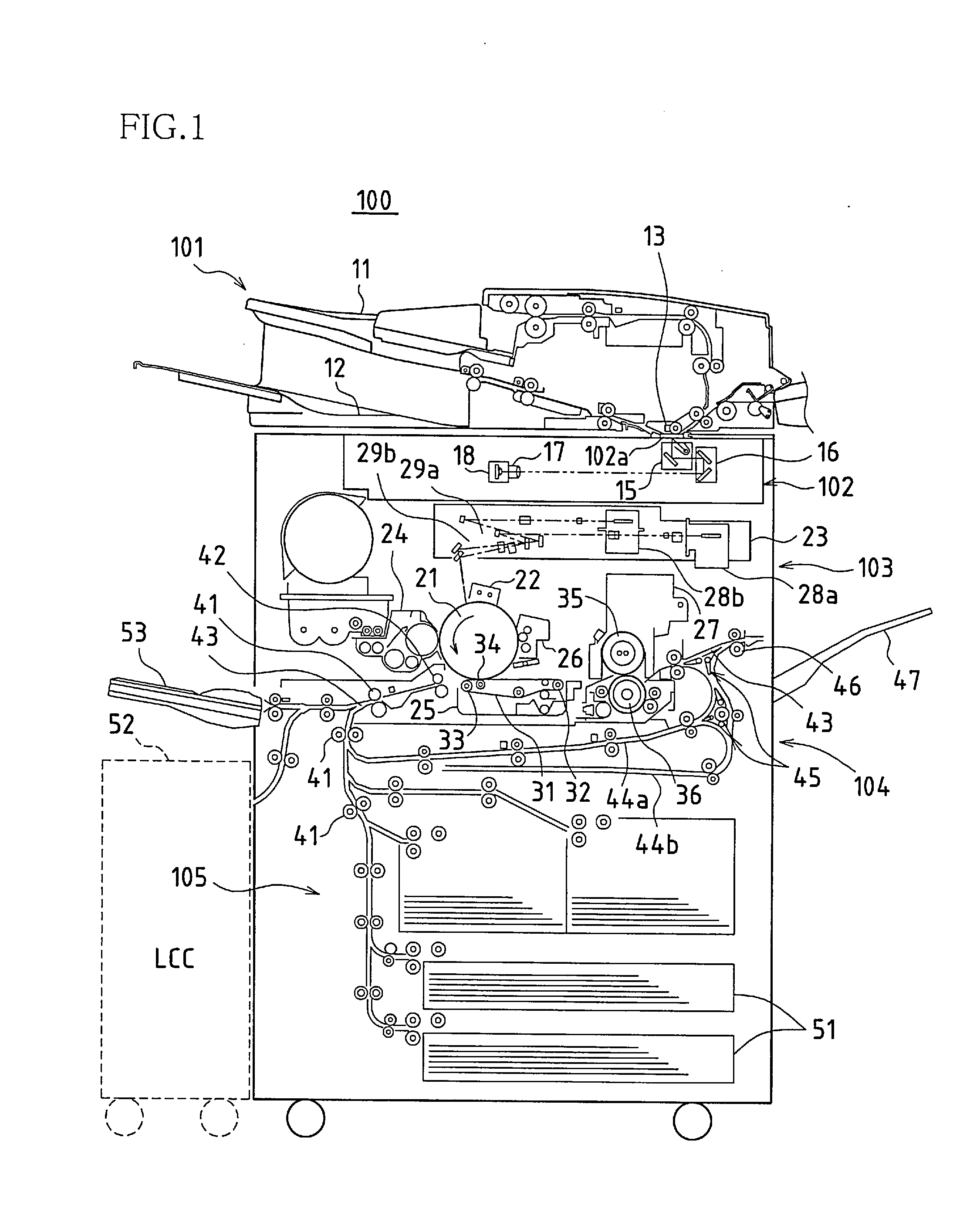
[0047]FIG. 1 is a schematic view of an image forming apparatus in which one embodiment of a fixing apparatus according to the present invention has been applied. An image forming apparatus 100 obtains image data that has been read from an original paper or obtains image data that has been received from outside, and forms a monochrome image represented by the image data on recording paper, and its structure can be broadly divided into an original paper transport portion (ADF) 101, an image reading portion 102, a print portion 103, a paper transport portion 104, and a paper feed portion 105.

[0048]When at least one sheet of an original paper is set in an original setting tray 11 in the original paper transport portion 101, the original paper is withdrawn and transported from the original setting tray 11 sheet by sheet, and the original paper is guided to and made...


PUM


Abstract

In one embodiment, a predetermined period different from a fixing process period in which fixing of toner to recording paper is carried out is set as a toner removal period, and during the toner removal period a hot roller and a pressure roller are intermittently rotated, and separation claws in contact with the rollers are caused to vibrate by the intermittent rotation of the rollers such that toner adhered to the separation claws is caused to drop due to this and is removed. Also, faces of the separation claws that oppose the surfaces of the hot roller and the pressure roller are set in a convex shape.

Description

CROSS-REFERENCE TO RELATED APPLICATIONS[0001]This application claims priority under 35 U.S.C. § 119(a) on Patent Application No. 2006-228189 filed in Japan on Aug. 24, 2006, the entire contents of which are hereby incorporated by reference.BACKGROUND OF THE INVENTION[0002]1. Field of the Invention[0003]The present invention relates to roller drive control methods of fixing apparatuses and fixing apparatuses in electrophotographic image forming apparatuses.[0004]2. Description of the Related Art[0005]In this type of fixing apparatus, while recording paper is sandwiched and transported in a nip region between a pair of fixing rollers, the recording paper is subjected to heat and pressure by the fixing rollers so as to thermally fuse and fix toner onto the recording paper.[0006]However, not all the toner is fused and fixedly attached onto the recording paper by the fixing process, and a small amount of toner transfers and adheres to the fixing roller side since the fixing rollers have ...

Claims


Application Information

Patent Timeline
Patent Type & Authority Applications(United States)
IPC IPC(8): G03G15/20
CPCG03G15/2025G03G15/2028
Inventor TATEISHI, YOSHINOBUTAKAI, YASUHIRO
Owner SHARP KK
Why Eureka
Try Eureka