Damper

Active Publication Date: 2008-10-16
NIFCO INC
View PDF7 Cites 12 Cited by
  • Summary
  • Abstract
  • Description
  • Claims
  • Application Information

AI Technical Summary

Benefits of technology

[0013]According to the invention, the wing portion is formed in an asymmetric shape with respect to the rotational direction relative to the straight line extending radially from the shaft portion. The tip side surface of the wing portion which is located on the tip side of the rotational direction when the rotor rotates in the damping torque generating direction, becomes the sloping surface which slopes to the back end side of the rotational direction from the tip side toward the outside of the radial direction from the inside of the radial direction. The back end side surface of the wing portion which is located on the back end side of the rotational direction when the rotor rotates in the damping torque generating direction, becomes the flat surface which runs parallel to the straight line extending radially. Also, the inner surface of the control valve member which faces the sloping surface, is the parallel sloping surface which runs parallel to the sloping surface, and the inner surface of the control valve member which faces the flat surface, is the parallel flat surface which runs parallel to the flat surface. Accordingly, even if the moving distance relative to the rotor (wing portion) of the control valve member is shortened, the circulation passage for the viscous fluid can be sufficiently maintained.
[0014]Therefore, the play of the control valve member can be shortened, so that the response of the control valve member improves.
[0015]The width of the tip portion of the control valve member with the parallel sloping surface, which is perpendicular to the shaft of the shaft portion, widens toward the outside of the radial direction from the inside of the radial direction. Accordingly, the length of the circumferential direction of the control valve member contacting the inner perimeter surface of the housing is prolonged or extended, so that the posture of the control valve member is stabilized, and its operation is stabilized.
[0016]In addition, the protruding wall extending in the circumferential direction is provided in the tip portion of the control valve member with the parallel sloping surface. Accordingly, pressurized viscous fluid in a damped state pushes the protruding wall in the radial direction and presses the control valve member against the inner perimeter surface of the housing. As a result, the posture of the control valve member is additionally stabilized.
[0017]Moreover, since the protruding wall contacts the inner perimeter surface of the housing, the posture of the control valve member is stabilized further.
[0018]Also, since the heat expansion coefficient of the control valve member is made below the heat expansion coefficient of the housing or the rotor, even if the temperature rises and the viscosity of the viscous fluid decreases, because orifices (gaps between the housing and the control valve member, and between the rotor and the control valve member) narrow, variation in the damping torque can be controlled.

Problems solved by technology

Therefore, during the reverse movement from the damping state to the non-damping state, or from the non-damping state to the damping state, the play (moving distance) of the control valve members becomes longer, so that response of the control valve members deteriorates.

Method used


Image

  • Damper
  • Damper
  • Damper

Examples


Embodiment Construction

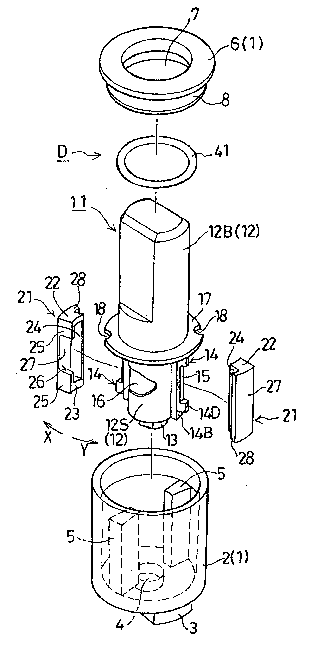
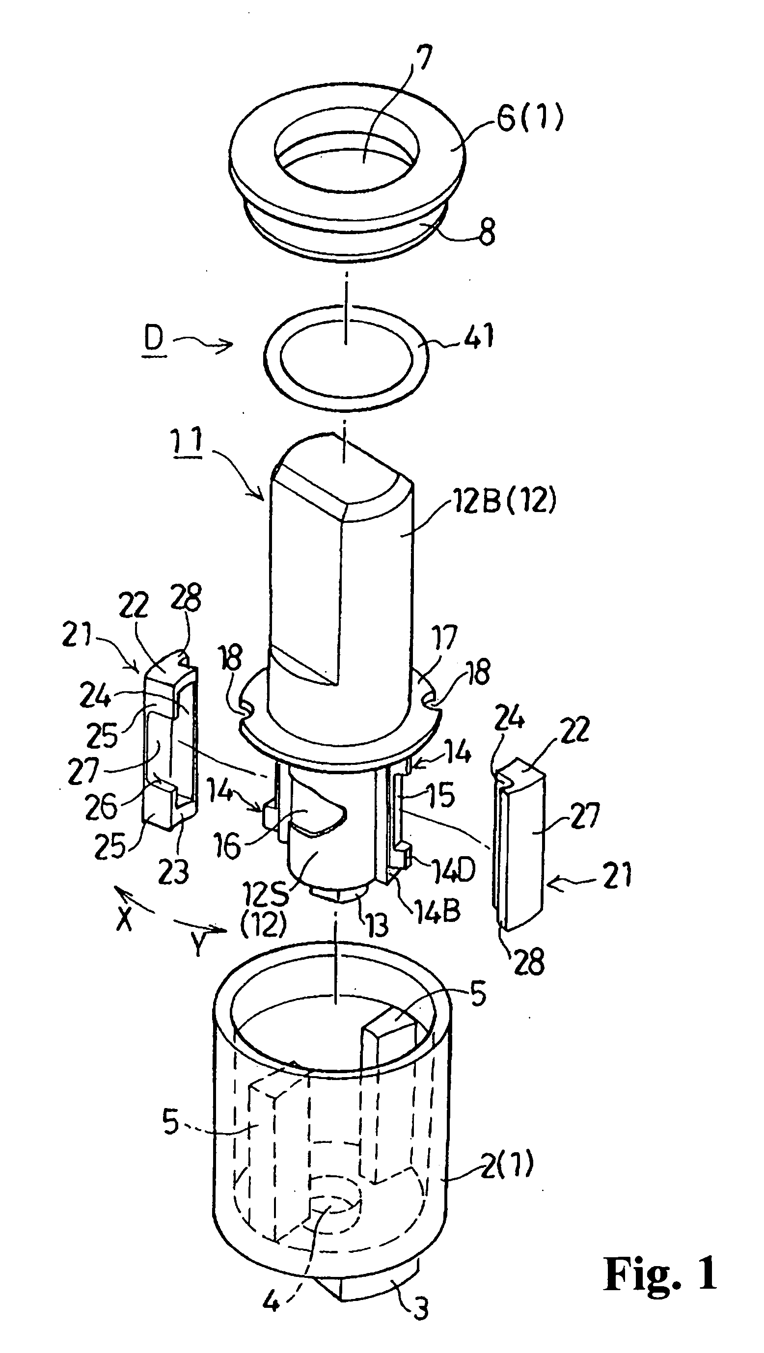
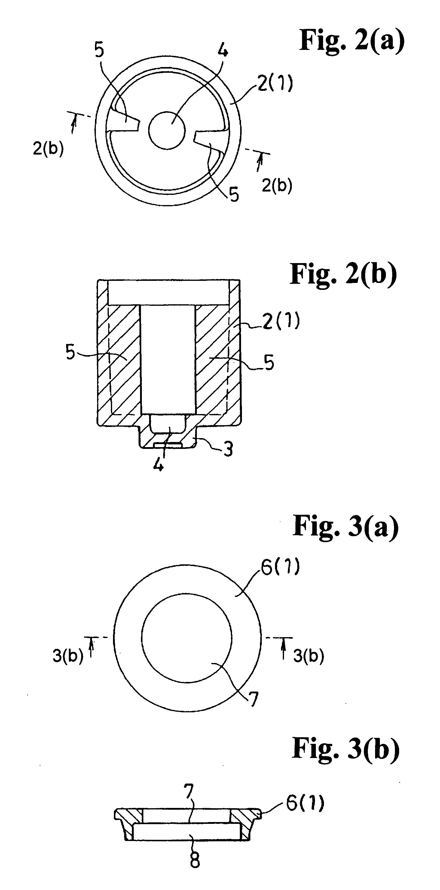
[0027]Hereunder, embodiments of the invention will be explained with reference to the accompanying drawings.

[0028]FIG. 1 is an exploded perspective view of a damper according to an embodiment of the invention; FIG. 2(a) is a plan view of a housing main body shown in FIG. 1, and FIG. 2(b) is a cross sectional view taken along line 2(b)-2(b) in FIG. 2(a); FIG. 3(a) is a plan view of a cap shown in FIG. 1, and FIG. 3(b) is a cross sectional view taken along line 3(b)-3(b) in FIG. 3(a); FIG. 4(a) is a plan view of a rotor shown in FIG. 1, FIG. 4(b) is a right side view of the rotor shown in FIG. 1, FIG. 4(c) is a bottom plan view of the rotor shown in FIG. 1, FIG. 4(d) is a cross sectional view taken along line 4(d)-4(d) in FIG. 4(b), and FIG. 4(e) is a cross sectional view taken along line 4(e)-4(e) in FIG. 4(b); FIG. 5(a) is an enlarged plan view of a control valve member shown in FIG. 1, FIG. 5(b) is an enlarged front view of the control valve member shown in FIG. 1, FIG. 5(c) is an ...


PUM


Abstract

A damper includes a cylindrical housing, a rotor rotatably disposed in the housing and having a cylindrical shaft portion and a wing portion radially outwardly extending from the shaft portion, a control valve member disposed between the housing and the shaft portion to cover the wing portion, and a viscous fluid filled inside the housing. The wing portion has an asymmetric shape with respect to a rotational direction of the rotor relative to a straight line extending radially from the shaft portion. The wing portion includes a tip side surface, and a back end side surface. The control valve member includes a first inner surface facing a sloping surface parallel thereto, and a second inner surface facing a flat surface parallel thereto.

Description

BACKGROUND OF THE INVENTION AND RELATED ART STATEMENT[0001]The invention relates to a damper which generates a damping torque only when a rotor rotates or turns relative to a housing in a damping torque generating direction.[0002]Conventionally, the above-mentioned damper includes a cylindrical housing; a rotor having a cylindrical shaft portion and wing portions formed on a part of the shaft portion and extending in a radial direction, the rotor being rotatably housed in the housing; control valve members, each being disposed between the housing and the part of the shaft portion and covering the wing portion; and a viscous fluid filled inside the housing. In this damper, the rotor rotates relative to the housing in a damping torque generating direction, so that the control valve members move relative to the rotor in a counter-damping torque generating direction, and block circulation passages for the viscous fluid. Accordingly, the damper assumes a damping state generating a dampin...

Claims


Application Information

Patent Timeline
IPC IPC(8): F16F15/121
CPCF16F9/145
Inventor NISHIYAMA, MASAYUKI
Owner NIFCO INC
Why Eureka
Try Eureka