
Collecting device

A collection device and collector technology, applied in fluid pressure actuation devices, separation methods, liquid variable volume machines, etc., can solve problems such as low collection efficiency, low collection efficiency, and clogging of filling layers.

Inactive Publication Date: 2005-06-29
EBARA CORP
View PDF0 Cites 0 Cited by
  • Summary
  • Abstract
  • Description
  • Claims
  • Application Information

AI Technical Summary

Problems solved by technology

However, it still has the problem that solid matter settles in the exhaust gas treatment equipment located downstream of the vacuum pump, thereby clogging a packing layer in the exhaust gas treatment equipment
However, in general, the collection efficiency of this commonly used collection device is not high, and about 60% of the exhaust components flow through the collection device without being adsorbed on the collector, but adsorbed on the downstream pipelines and equipment
This is mainly because the discharged gaseous state flows through the section with low collection efficiency between the inner wall of the container and the collector of the collection device, thus passing through the collection device without being collected

Method used


Image

  • Collecting device
  • Collecting device
  • Collecting device

Examples


Embodiment Construction

[0051] A collecting device according to an embodiment of the present invention will be described below with reference to the accompanying drawings. The same or corresponding parts are denoted by the same or corresponding reference numerals throughout the drawings.

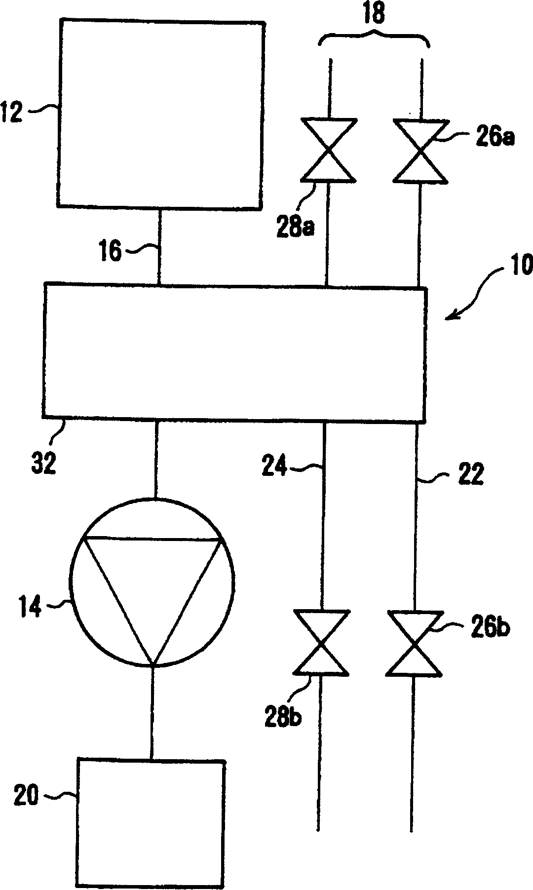
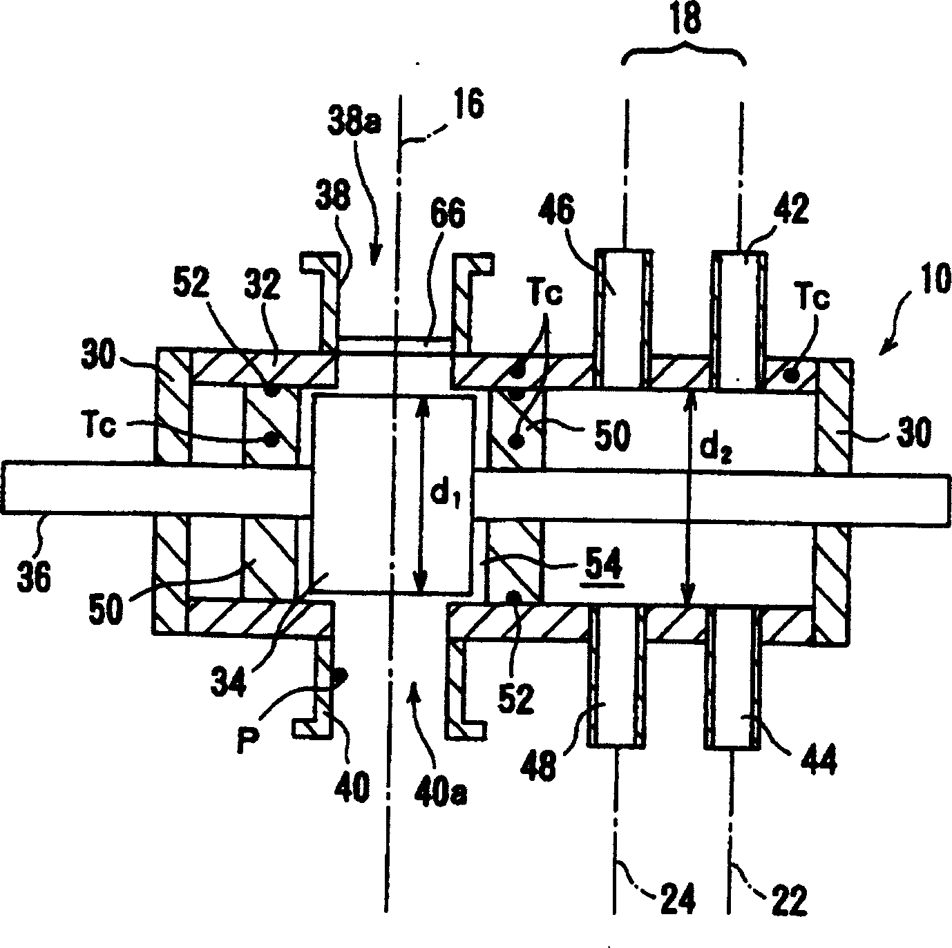
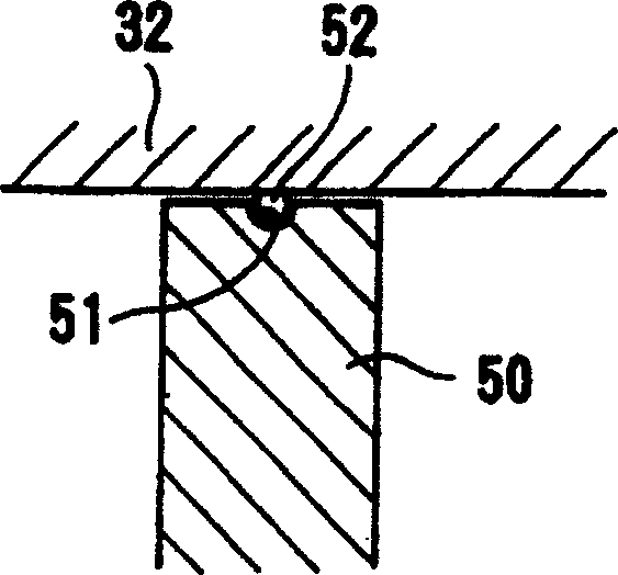
[0052] Figures 1 to 3 A collection device representing a first embodiment of the present invention. The collection device 10 crosses and extends through the exhaust channel 16 and the regeneration channel 18 so that the airtight sealed chamber 12 can be evacuated by the vacuum pump 14 , and the regeneration channel 18 is disposed adjacent to the exhaust channel 16 . In this embodiment, vacuum pump 14 is a single stage vacuum pump. On the other hand, multi-stage vacuum pumps can also be used. An exhaust treatment device 20 that removes toxic substances from exhaust gas is provided downstream of the vacuum pump 14 . The regeneration channel 18 has a line 22 for cleaning liquid and a line 24 for drying gas. In t...


PUM


Abstract

A collection device, which includes: an exhaust channel, used to evacuate the airtight sealed chamber by a vacuum pump; an airtight sealing collection container, extending through the exhaust channel and a regeneration channel adjacent to the exhaust channel; a collection A collector, located in the collection container to absorb the product in the discharged gas, and remove the product from the discharged gas, the collector is selectively located on the exhaust channel or the regeneration channel; a valve member, located on both sides of the collector , which can move integrally with the collector; a sealing member, which is installed on the outer peripheral surface of the valve member, so that the collector can slide on the inner peripheral surface of the collection container when it is moved.

Description

technical field [0001] The present invention relates to a collection device used in an evacuation system for evacuating a vacuum chamber of semiconductor manufacturing equipment or the like. Background technique [0002] Refer to the attached Figure 16 A commonly used evacuation system will be described. exist Figure 16 Here, a hermetically sealed chamber 201 includes a processing chamber used in a semiconductor manufacturing process, such as an etching device or a chemical vapor deposition (VCD) device. The hermetically sealed chamber 201 is connected to a vacuum pump 203 through an exhaust channel 202 . The vacuum pump 203 is used to increase the pressure of the gas exhausted from the hermetically sealed chamber 201 to atmospheric pressure during the exhaust process. Therefore, an oil-sealed rotary vacuum pump is used as the vacuum pump 203 . Currently, a dry pump is mainly used as the vacuum pump 203 . [0003] If the required vacuum degree of the hermetically seale...

Claims


Application Information

Patent Timeline
Patent Type & Authority Patents(China)
IPC IPC(8): H01L21/205B01D8/00B01D53/02B01D53/14B01D53/34C23C16/44
CPCB01D8/00B01D53/02B01D53/14B01D53/34C23C16/4412
Inventor 野村典彦
Owner EBARA CORP
Learn More