Powered Orthosis

a technology of powered orthosis and power supply, which is applied in the field of powered orthosis, can solve the problems of significant muscle weakness or impairment in motor control, patients experiencing such injury often have substantial limitations in movement, and passive devices cannot supply energy to the leg

Inactive Publication Date: 2008-10-16
UNIVERSITY OF DELAWARE
View PDF8 Cites 95 Cited by
  • Summary
  • Abstract
  • Description
  • Claims
  • Application Information

AI Technical Summary

Benefits of technology

[0008]One aspect of the invention comprises a powered orthosis adapted to be secured to a corresponding body portion of a user for guiding motion of the user. The orthosis comprises a plurality of structural members and one or more joints adjoining adjacent structural members. Each joint has one or more degrees of freedom and a range of joint angles. One or more of the joints comprises at least one back-drivable actuator governed by at least one controller for controlling the joint angle. The one or more joint actuator controllers are synchronized to cause the corresponding joint actuators to generate forces for assisting the user to move the orthosis at least in part under the user's power along a desired trajectory within an allowed tolerance. The joint controllers may comprise set-point controllers or force-field controllers. In an embodiment in which the joint controllers comprise force-field controllers that define a virtual tunnel for movement of the orthosis, the forces applied to the orthosis for assisting the user are proportional to deviation from the desired trajectory, and may include tangential forces along the trajectory and normal forces perpendicular to the trajectory. Tangential forces are inversely proportional to the deviation from the desired trajectory, whereas the normal forces are directly proportional to the deviation from the desired trajectory.

Problems solved by technology

Neurological injury, such as hemiparesis from stroke, results in significant muscle weakness or impairment in motor control.
Patients experiencing such injury often have substantial limitations in movement.
Passive devices cannot supply energy to the leg, however, and are therefore limited in their ability compared to active devices.
A limiting feature of existing active devices, however, is that they move a subject through a predestined movement pattern rather than allowing the subject to move under his or her own control.
The failure to allow patients to self-experience and to practice appropriate movement patterns may prevent changes in the nervous system that are favorable for relearning, thereby resulting in “learned helplessness,” which is sub-optimal.
Fixed repetitive training may cause habituation of the sensory inputs and may result in the patient not responding well to variations in these patterns.

Method used


Image

  • Powered Orthosis
  • Powered Orthosis
  • Powered Orthosis

Examples


Embodiment Construction

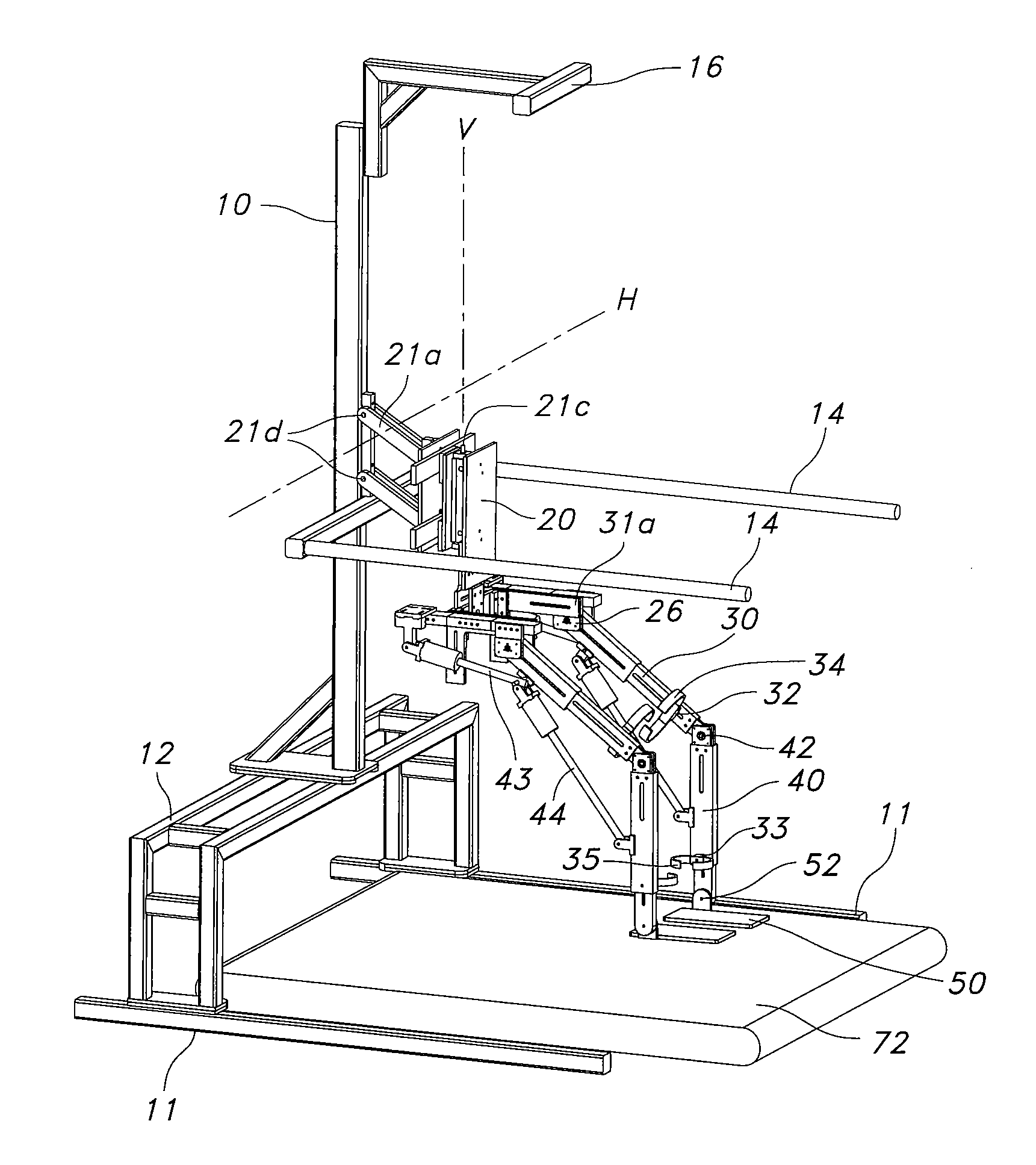
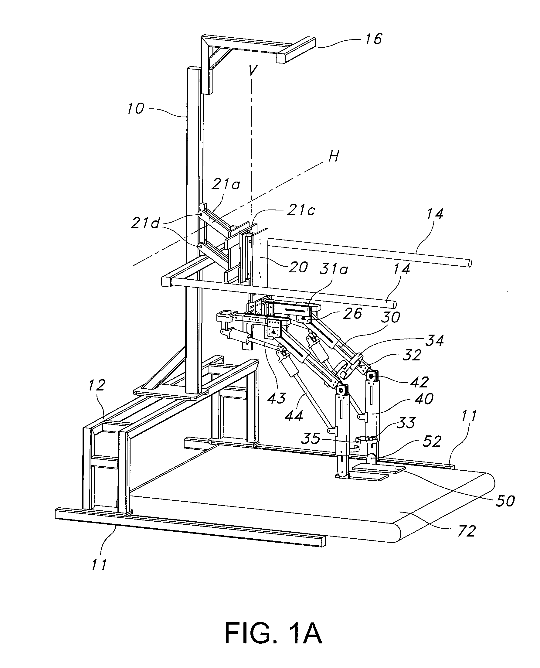
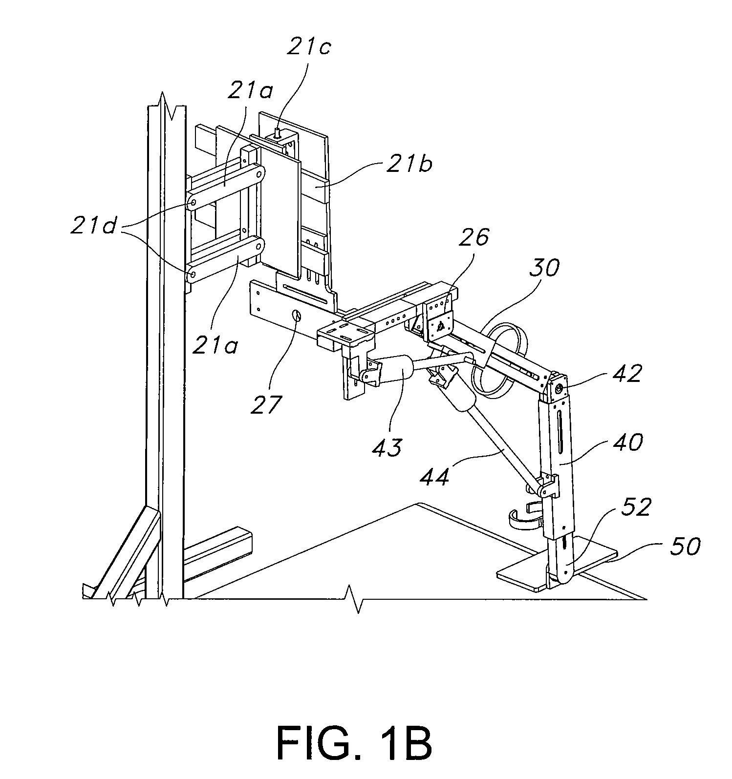
[0032]Referring now to the drawings, an exemplary powered leg orthosis is schematically illustrated in FIGS. 1A-1B. The exemplary orthosis is based upon the prototype passive Gravity Balancing Leg Orthosis described in the '729 application. The overall setup comprises frame 10, trunk 20, thigh segment 30, shank segment 40, and foot segment 50. Frame 10 takes the weight of the entire device. Trunk 20 is connected to the frame through a plurality of trunk joints 21a-21d having four degrees-of-freedom. These degrees-of-freedom are vertical translation provided by parallelogram mechanism 21a having revolute joints 21d, lateral translation via slider-block and slider-bar 21b, rotation about vertical axis V at revolute joint 21c, and rotation about horizontal axis H perpendicular to sagittal plane S at revolute joints 21d. User 22 is secured to trunk 20 of the orthosis with a hip brace 24.

[0033]Thigh segment 30 has two degrees-of-freedom with respect to trunk of the orthosis: translation ...


PUM


Abstract

A powered orthosis, adapted to be secured to a corresponding body portion of the user for guiding motion of a user, the orthosis comprising a plurality of structural members and one or more joints adjoining adjacent structural members, each joint having one or more degrees of freedom and a range of joint angles. One or more of the joints each comprise at least one back-drivable actuator governed by a controller for controlling the joint angle. The plurality of joint controllers are synchronized to cause the corresponding actuators to generate forces for assisting the user to move the orthosis at least in part under the user's power along a desired trajectory within an allowed tolerance. One embodiment comprises force-field controllers that define a virtual tunnel for movement of the orthosis, in which the forces applied to the orthosis for assisting the user may be proportional to deviation from the desired trajectory.

Description

CROSS-REFERENCE TO RELATED APPLICATIONS[0001]This application claims priority to U.S. Provisional Patent Application Ser. No. 60 / 922,216, filed Apr. 6, 2007, incorporated herein by reference.STATEMENT REGARDING FEDERALLY SPONSORED RESEARCH[0002]The U.S. Government has a paid-up license in this invention and the right in limited circumstances to require the patent owner to license others on reasonable terms as provided for by the terms of NIH Grant #1 RO1 HD38582-01A2, awarded by the National Institutes of Health.FIELD OF THE INVENTION[0003]The present invention relates to an apparatus for assisting a user to move an extremity in a desired trajectory, such as an apparatus for applying forces to a user's leg to assist in gait rehabilitation of a patient with walking disabilities.BACKGROUND OF THE INVENTION[0004]Neurological injury, such as hemiparesis from stroke, results in significant muscle weakness or impairment in motor control. Patients experiencing such injury often have substa...

Claims


Application Information

Patent Timeline
Patent Type & Authority Applications(United States)
IPC IPC(8): A61F5/00A61F2/48
CPCA61H2201/5061A63B21/00181A63B22/0235A63B24/0006A63B69/0064A63B71/0009A63B2024/0009A63B2220/16A63B2220/54A61H2201/123A61H1/0262A61H3/008A61H2201/1623A61H2201/1635A61H2201/1642A61H2201/1676A61H1/0255A61H2201/163
Inventor AGRAWAL, SUNILBANALA, SAI
Owner UNIVERSITY OF DELAWARE
Why Eureka
Try Eureka