Multiple Stent Delivery System and Method

a stent and multi-stent technology, applied in the field of medical devices and procedures, can solve the problems of more difficult manipulation of the sheath and stent than for shorter stents, and achieve the effects of easy operation, increased friction resistance, and improved stability

Inactive Publication Date: 2008-10-16
MEDTRONIC VASCULAR INC
View PDF23 Cites 103 Cited by
  • Summary
  • Abstract
  • Description
  • Claims
  • Application Information

AI Technical Summary

Benefits of technology

[0017]A physician manipulating the middle member and sheath must exert a force to overcome a lesser amount of frictional resistance force associated with moving a short stent (which exerts the radial force on the sheath proportional to its length) within the sheath compared to the higher frictional resistance force needed to move a longer (or multiple stents) with a frictional resistance force proportionally higher, the frictional resistance force expected to be proportional to the stent lengths that are being moved simultaneously at any one time. When manipulating long stent lengths, the higher compressive and tensile stresses placed on the middle member and sheath respectively, to overcome the larger frictional resistance forces associated with long stent lengths, make manipulation of the sheath and stent del

Problems solved by technology

When manipulating long stent lengths, the higher compressive and tensile stresses placed on the middle member and sheath respectively, to overcome the larger frictional res

Method used


Image

  • Multiple Stent Delivery System and Method
  • Multiple Stent Delivery System and Method
  • Multiple Stent Delivery System and Method

Examples


Embodiment Construction

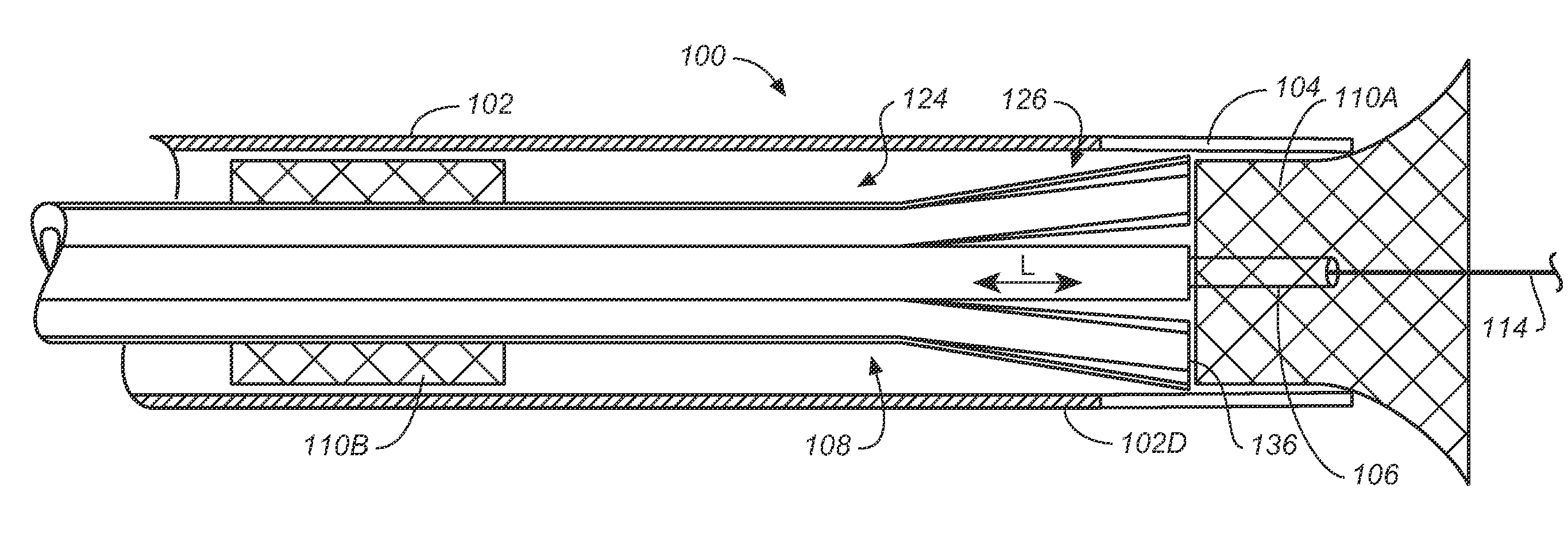
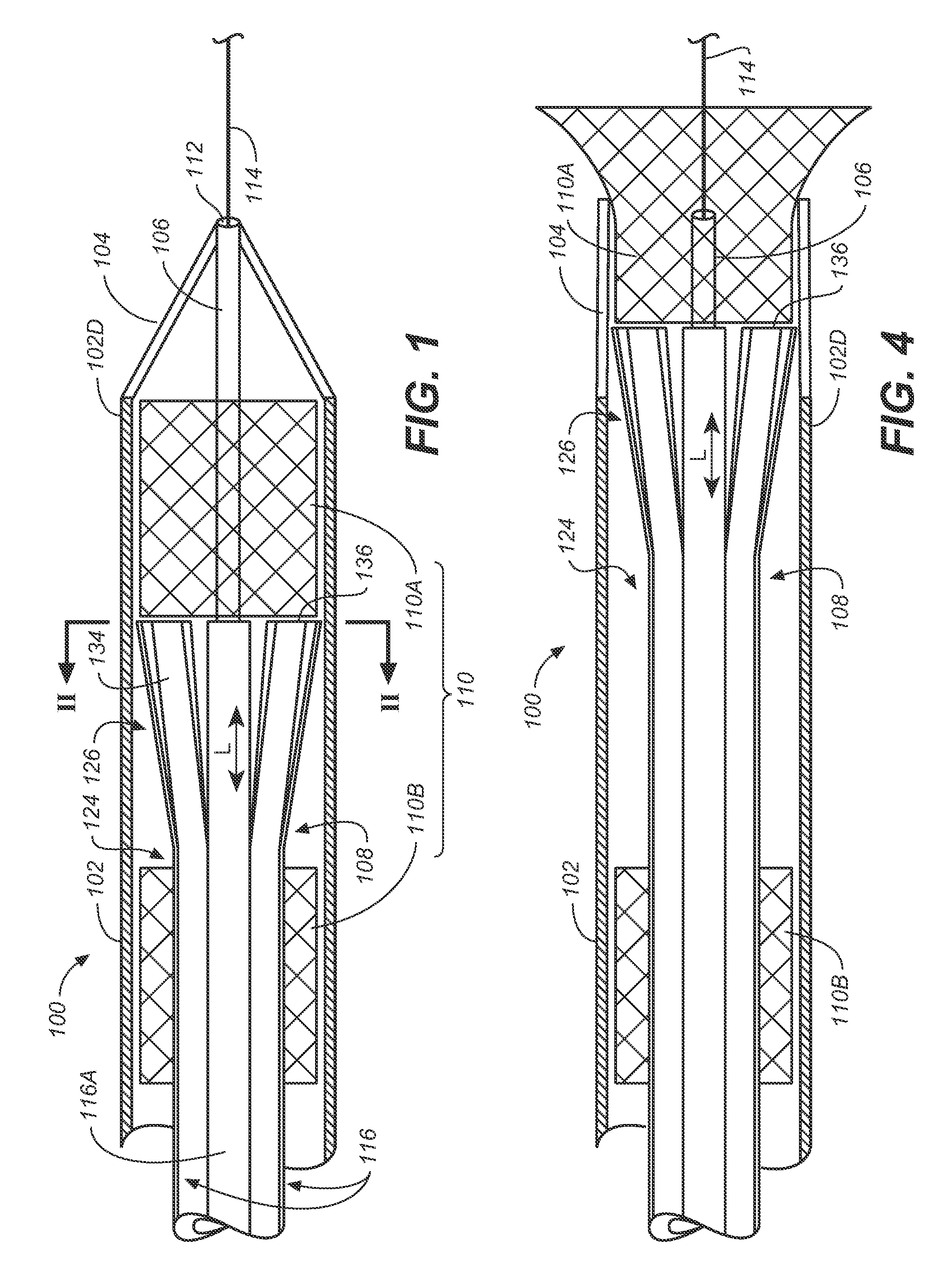
[0031]Referring to FIG. 1, a method of deploying multiple stents using a multiple stent delivery system includes moving a distal stent 110A into contact with a stent-pushing face 136 of a compressible expanded tip 126 of an inner member 108. Referring to FIG. 4, a sheath 102 is retracted relative to inner member 108 to deploy distal stent 110A by holding the distal stent 110A stationary with inner member 108 as sheath 102 is withdrawn.

[0032]Referring to FIGS. 5 and 7 together, sheath 102 is advanced relative to inner member 108 to reposition a next proximal stent 110B for deployment by passing compressible expanded tip 126 through proximal stent 110B. Sheath 102 is again retracted relative to inner member 108 to engage the proximal stent 110B by pushing proximal stent 110B distally through sheath 102 with inner member 108 to a pre-deployment condition / position, e.g., as shown in FIG. 1. The next proximal stent is then deployed from that position in a manner similar to that illustrat...


PUM


Abstract

A method of deploying multiple stents using a multiple stent delivery system includes moving a distal stent into contact with a stent-holding surface of a compressible expanded tip of an inner member. A sheath is retracted relative to the inner member to deploy the distal stent by holding the distal stent stationary with the inner member and retracting the sheath. The sheath is advanced relative to the inner member to reposition a proximal stent to capture, be positioned behind a next stent to be deployed by being compressed and passing the compressible expanded tip through the next proximal stent. The sheath is retracted relative to the inner member to bring the next stent to a pre-deployment position and then deployment of the next proximal stent can take place as already performed for the first deployed stent.

Description

BACKGROUND OF THE INVENTION[0001]1. Field of the Invention[0002]This invention relates generally to medical devices and procedures, and more particularly to a method and system of deploying stents in a vascular system.[0003]2. Description of Related Art[0004]Prostheses for implantation in blood vessels or other similar organs of the living body are, in general, well known in the medical art. For example, “self-expanding” stents are stents inserted into the vascular system in a compressed or contracted state, and permitted to expand upon removal of a restraint. Self-expanding stents typically employ a wire or tube configured (e.g., bent or cut) to provide an outward radial force and employ a suitable elastic material such as stainless steel or Nitinol (nickel-titanium). Nitinol may additionally employ shape memory properties.[0005]A self-expanding stent is typically sized to be configured in a tubular shape of a slightly greater diameter than the diameter of the blood vessel in which...

Claims


Application Information

Patent Timeline
IPC IPC(8): A61F2/84A61F2/82A61F2/90
CPCA61F2/90A61F2/95A61F2/966A61F2002/826
Inventor SCHKOLNIK, DANIEL
Owner MEDTRONIC VASCULAR INC
Why Eureka
Try Eureka