Method of Adjusting Origin of Industrial Robot

a technology of industrial robots and origins, applied in the direction of mechanical control devices, programme control, instruments, etc., can solve the problems of increasing increasing the working time, hurting the position pin and the arm, etc., and achieve the effect of reducing the work load on the operator

Active Publication Date: 2008-10-16
PANASONIC CORP
View PDF8 Cites 0 Cited by
  • Summary
  • Abstract
  • Description
  • Claims
  • Application Information

AI Technical Summary

Benefits of technology

[0007]This method prevents a possible failure of the attaching of the positioning member, and decreases a work load on an operator.

Problems solved by technology

An operation of adjusting the origin requires accuracy, thus increasing a work load on the operator and increasing a working time.
An erroneous handling by the operator during adjusting the origin may hurt the position pin and the arm.
If the operator fails to attach the positioning member, the origin is not adjusted properly.
If the operator fails to detach the positioning member after the adjusting of the origin adjustment and activates the robot, the positioning member and the arm of the robot arm may be damaged.

Method used


Image

  • Method of Adjusting Origin of Industrial Robot
  • Method of Adjusting Origin of Industrial Robot
  • Method of Adjusting Origin of Industrial Robot

Examples


Embodiment Construction

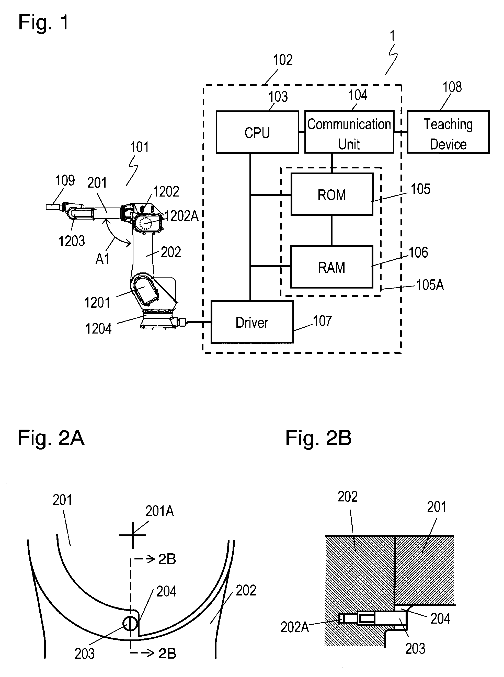
[0038]FIG. 1 is a schematic view of industrial robot 1 according to an exemplary embodiment of the present invention. Industrial robot 1 includes manipulator 101, tool 109 mounted on manipulator 101, controller 102 for controlling manipulator 101, and teaching device 108 used for activating manipulator 101 and controller 102. Tool 109 may be various devices, such as a welding torch and an opening / closing hand, according to the purpose.

[0039]Controller 102 includes CPU 103, communication unit 104 for communicating with teaching device 108, ROM 105 storing a program allowing CPU 103 to operate, RAM 106 storing variable data, such as an operation program instructed by an operator and data for establishing an operating environment, and driver 107 for driving manipulator 101. ROM 105 and RAM 106 provide memory 105A.

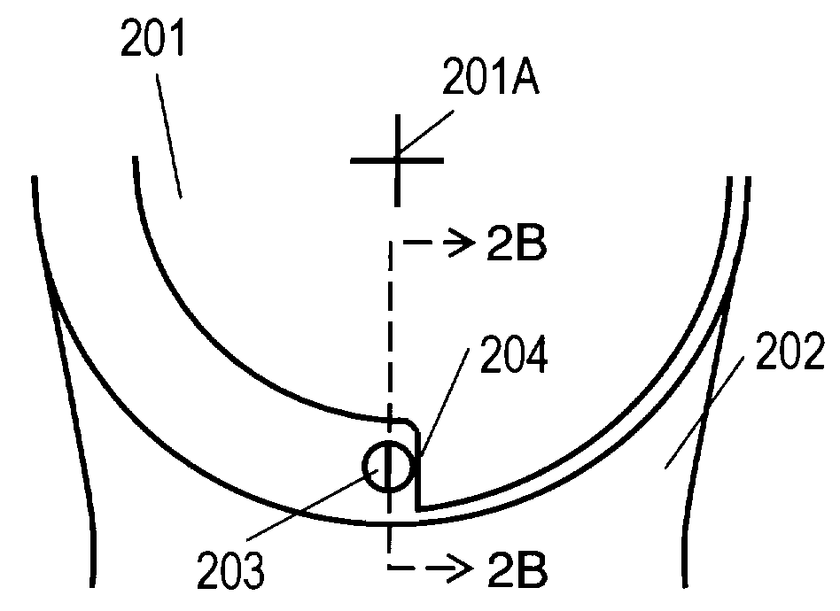
[0040]Manipulator 101 includes arms 202 and 201 rotating with respect to each other, base 1204, joint 1202 coupling arm 201 with arm 202, joint 1201 coupling arm 202 with base...


PUM


Abstract

An industrial robot includes a first member, a positioning member arranged to be attached to the first member, a second member arranged to rotate relatively to the first member, and a first joint for coupling the first member with the second member. The second member has a contact point arranged to contact the positioning member. An indication for requesting to enabling the positioning member to contact the contact point is displayed. The second member rotates at the first joint relatively to the first member while the positioning member can contact the contact point. It is detected whether or not the contact point of the second member contacts the positioning member. A position of the second member is stored as an origin when it is detected that the contact point of the second member contacts the positioning member. This method prevents a possible failure of the attaching of the positioning member, and decreases a work load on an operator.

Description

TECHNICAL FIELD[0001]The present invention relates to a method of adjusting an origin of a joint of an industrial robot.BACKGROUND OF THE INVENTION[0002]In an operation of an industrial robot, an angle of a joint of a manipulator calculated by a processor, such as a CPU, for activating the joint is correlated to an actual angle of the joint. For this purpose, an origin, a reference of a rotation of the joint is adjusted.[0003]FIG. 6 shows a conventional apparatus for adjusting the origin disclosed in Japanese Patent Laid-Open Publication No. 2-180580. Member 611 rotates about rotation axis 620 with reference to member 612. Recess 613 is provided in the circumference of member 611 at a position corresponding to an origin. Adjusting device 630 detachable from member 612 is attached the position corresponding to the origin. Adjusting device 630 includes switch holder 615 fixed on member 612 at the position corresponding to the origin, switch 614 held by switch holder 615, straight bear...

Claims


Application Information

Patent Timeline
Patent Type & Authority Applications(United States)
IPC IPC(8): B25J9/10
CPCY10T74/2063B25J9/101
Inventor IKEDA, TATSUYANAKATA, HIROYUKIIWAI, SEIJI
Owner PANASONIC CORP
Why Eureka
Try Eureka