On-vehicle data collection apparatus, center, and on-vehicle system

a data collection and vehicle technology, applied in vehicle testing, structural/machine measurement, instruments, etc., can solve the problem of not being able to flexibly and complicatedly set the timing of recording freeze data from outside the vehicl

Inactive Publication Date: 2008-10-16
DENSO CORP
View PDF8 Cites 110 Cited by
  • Summary
  • Abstract
  • Description
  • Claims
  • Application Information

AI Technical Summary

Benefits of technology

[0008]According to a third aspect of the present invention, an on-vehicle system includes a first communication apparatus configured to detect abnormality of a vehicle and coupled to an in-vehicle communication network and multiple second communication apparatus, each of which is coupled to the network and configured to communicate with the first communication apparatus through the network. The first communication apparatus transmits abnormality notice information indicative of the detected abnormality over the network upon detection of the abnormality Each second co

Problems solved by technology

However, the technology disclosed in JP-A-H9-126954 merely outputs a trigger signal to an external device at the timing of st

Method used


Image

  • On-vehicle data collection apparatus, center, and on-vehicle system
  • On-vehicle data collection apparatus, center, and on-vehicle system
  • On-vehicle data collection apparatus, center, and on-vehicle system

Examples


first embodiment

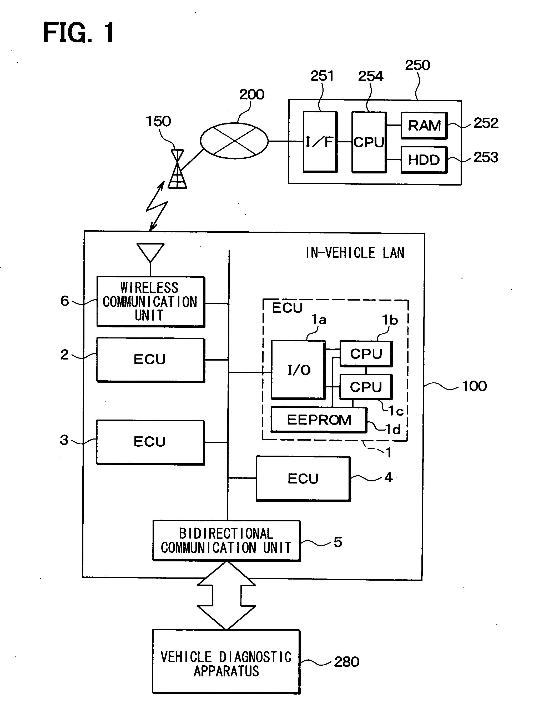
[0032]FIG. 1 schematically shows an overall construction of a vehicle system 100 according to a first embodiment of the present invention and its peripheral devices. The vehicle system 100 is mounted on a vehicle. The vehicle system 100 can exchange signals with a vehicle diagnostic apparatus 280 outside the vehicle. The vehicle system 100 can communicate with a distant management center 250, for example, via a base station 150 and a network 200 (e.g., a wide area network (WAN) such as the Internet, leased line, or the like).

[0033]As shown in FIG. 1, the vehicle system 100 includes various types of electronic control units (ECUs) 1-4 to control actuators (not shown in the drawing) mounted on the vehicle and obtain states of the vehicle by using sensors (not shown in the drawing) mounted on the vehicle. Further, the vehicle system 100 includes a bidirectional communication unit 5 and a wireless communication unit 6. The bidirectional communication unit 5 mediates the exchange of sign...

second embodiment

[0109]A second embodiment of the present invention is described below. This embodiment assumes that the vehicle system 100 as described in the first embodiment is mounted in plural vehicles. The management center 250 communicates with ECUs in the plural vehicle systems 100, selects the same types of vehicle systems from among the plural vehicle systems 100, and transmits same condition signals to ECUs of the same types of vehicle systems 100.

[0110]FIG. 14 schematically shows the construction of the management center 250 of this embodiment. The hard disk drive 253 of the management center 250 of this embodiment stores a failure information DB 253a and a vehicle destination DB 253b to achieve the above-described operation. FIG. 15 shows the data structure of the failure information DB 253a. The failure information DB 253a contains plural records corresponding to vehicles (that is, the vehicle system 100) different from each other. Each record includes a VIN code field, a mounted senso...

third embodiment

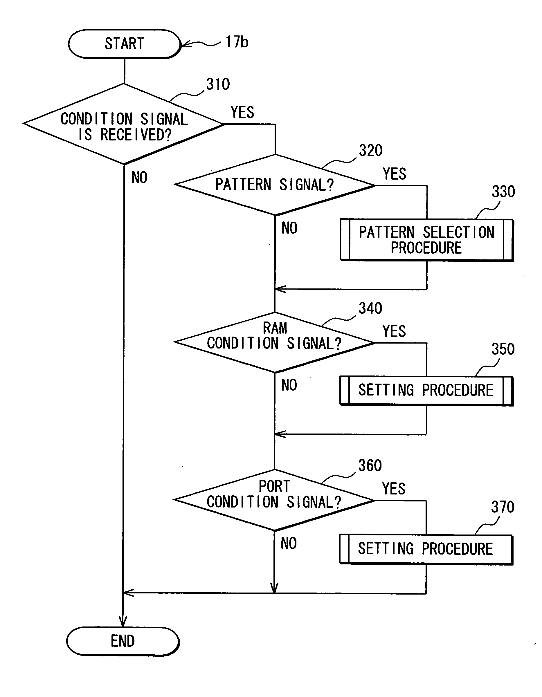
[0126]The following describes a third embodiment of the present invention. This embodiment shows an example of a procedure by which an operator of a vehicle dealer or the like analyzes vehicle failure by using the management center 250 described in the second embodiment or the vehicle diagnostic apparatus 280 described in the first embodiment. FIG. 17 is a flowchart showing the procedure.

[0127]The operator recognizes the occurrence of abnormality of the vehicle (step 910). The recognition may be realized as shown in the second embodiment in which the management center 250 is used to acquire vehicle failure information from each CPU of the vehicle system 100 of the vehicle, by acquiring diagnosis code from each CPU of the vehicle system 100 by using the vehicle diagnostic apparatus 280, or receiving a report of a sense of incongruity of the vehicle from the vehicle user.

[0128]On recognizing vehicle abnormality, the operator reads pattern information of each CPU in the vehicle system ...


PUM


Abstract

In a data collection apparatus mounted on a vehicle, an electric control unit sets an abnormality detection condition to detect abnormality of the vehicle based on a condition signal received from an external apparatus located outside the vehicle. The electric control unit determines whether the detection condition is satisfied and stores vehicle control data or vehicle behavior data upon satisfaction of the detection condition as freeze data. The abnormality of the vehicle is analyzed using the freeze data.

Description

CROSS REFERENCE TO RELATED APPLICATION[0001]This application is based on and incorporates herein by reference Japanese Patent Application No. 2007-105700 filed on Apr. 13, 2007.FIELD OF THE INVENTION[0002]The present invention relates to an on-vehicle data collection apparatus that stores data indicating behavior of a vehicle or control of the vehicle, relates to a center communicating with the data collection apparatus, and relates to an on-vehicle data collection system constructed with multiple data collection apparatus.BACKGROUND OF THE INVENTION[0003]Conventionally, a data collection apparatus is known that has a function to detect a failure of sensors and actuators mounted to a vehicle, and with the detection of the failure as a trigger, stores data indicating the behavior of the vehicle before and after the failure or data indicating the control of the vehicle as freeze data. The freeze data is used to determine the cause of a failure of the vehicle at a dealer or the like of...

Claims


Application Information

Patent Timeline
IPC IPC(8): G01M17/00G06F3/06
CPCG07C5/008G07C5/085
Inventor YAMADA, MITSUO
Owner DENSO CORP
Why Eureka
Try Eureka