Soap-dispensing faucet structure

a faucet and faucet body technology, applied in the direction of liquid transfer devices, dispensers, holders, etc., can solve the problems of impede the smooth emission of cleaning liquid, the hose 83/b> can easily be hooked or wound up, and the conventional faucet structure, etc., to achieve safe and hygienic, efficient boosting the convenience of application

Inactive Publication Date: 2008-10-23
PONY SANITARY WARE INDAL CORP
View PDF9 Cites 23 Cited by
  • Summary
  • Abstract
  • Description
  • Claims
  • Application Information

AI Technical Summary

Benefits of technology

[0004]It is, therefore, the primary purpose of the present invention to provide a soap-dispensing faucet structure, comprising an upright cylindrical faucet body having an upper section defined by an appropriate-depth receiving chamber to which a sleeve cover and a pump device are joined to form an individual soap-receiving accommodation space that is separated from another individual faucet water-discharging space disposed at the lower section of the faucet body, combining the upper and lower spaces into one integral unit wherein the soap-receiving accommodation space forms a depth-extending accommodating chamber that not only increases its capacity to contain liquid soap, but also facilitates speedy filling or refilling of the liquid soap, significantly reducing the cost of production and the space occupied as well as facilitating speedy assembly and maintenance thereby.
[0005]It is, therefore, the second purpose of the present invention to provide a soap-dispensing faucet structure wherein the faucet matched to a handle is combined with the soap-receiving accommodation space to form a set of integral but separate upper and lower chambers so that the water-discharging or the soap-dispensing can be flexibly operated in individual spaces without hindering each other, efficiently boosting the convenience of application thereby. In addition, a spout and a tube seat with the faucet handle mounted thereto are provided to respectively extend perpendicularly to the faucet body, while the pump device with the sleeve cover is mounted to extend on top of the receiving chamber of the faucet body, providing a unique spatial design with concise and whole depth-extending visual effects as well as achieving a safe and hygienic soap-dispensing faucet structure thereby.

Problems solved by technology

There are some drawbacks to such conventional faucet structure.
As a result, the hose 83 can easily get hooked or wound up and hinder the smooth emission of the cleaning liquid thereof.
Thus, the deteriorated cleaning liquid can easily breed bacteria therein, which is quite inconvenient and unhygienic in application.
Thus, the conventional faucet with a soap dispenser is complicated in structure and time-consuming in assembly.
In addition, it also occupies a lot of space, which makes it look rather awkward in appearance.

Method used


Image

  • Soap-dispensing faucet structure
  • Soap-dispensing faucet structure
  • Soap-dispensing faucet structure

Examples


Embodiment Construction

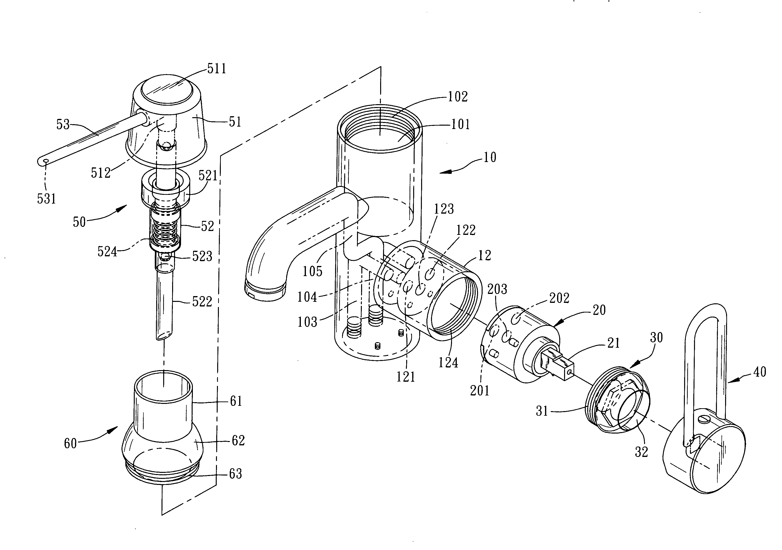
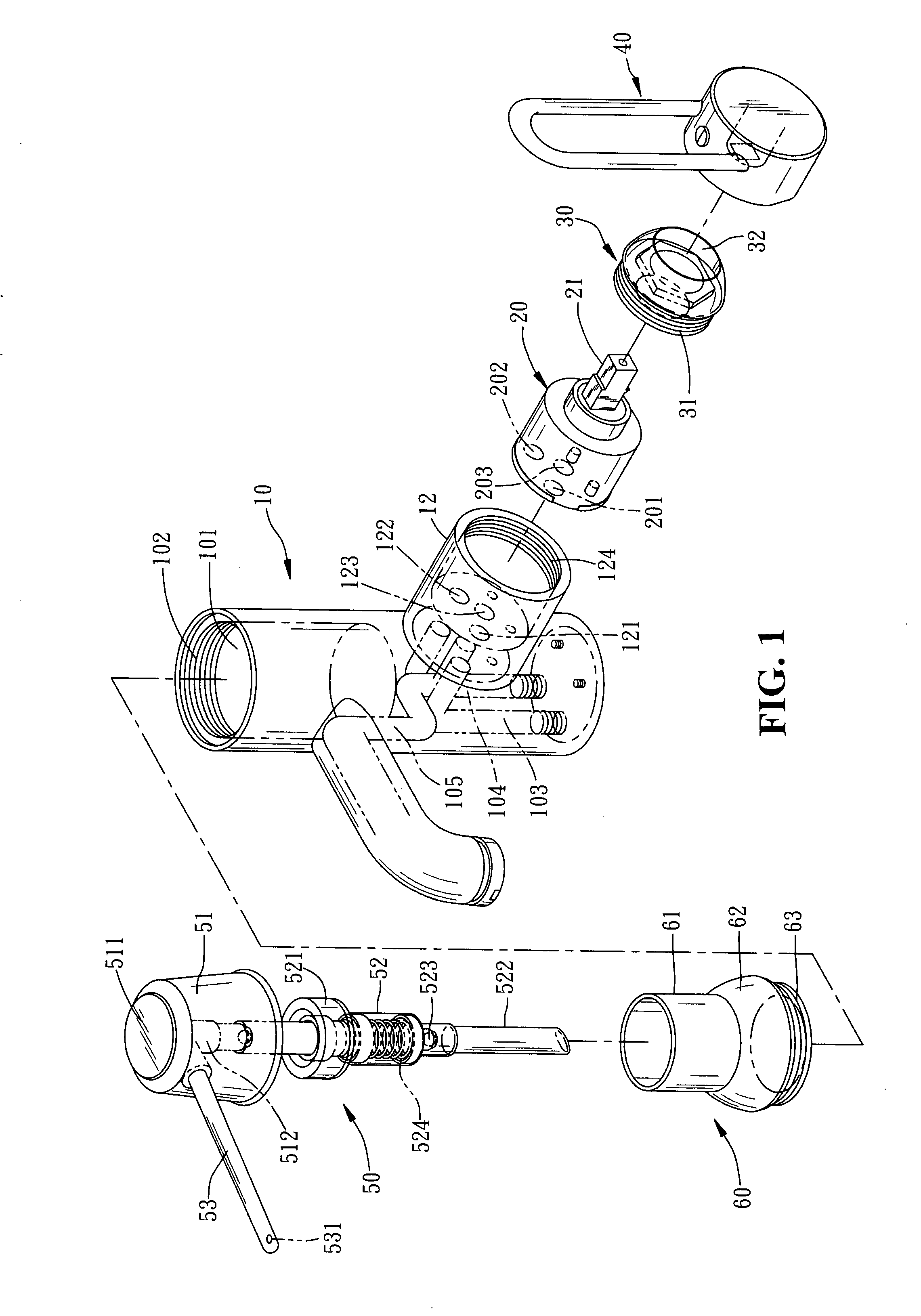
[0012]Please refer to FIG. 1 showing an exploded perspective view of the present invention. The present invention relates to a soap-dispensing faucet structure, comprising a faucet body 10, a core shaft 20 equipped with a spindle 21, a locking cap 30, a faucet handle 40, a pump device 50 and a sleeve cover 60. The faucet body 10 is molded into a cylindrical tube shape, having an arched spout 11 extending perpendicularly outwards for an appropriate length at the front of the upper section thereon, and a tube seat 12 extending perpendicularly outwards at one side of the lower section thereon wherein the tube seat 12 is defined by an appropriate-depth cavity with an internal-threaded locking section 124 disposed at the end edge thereon, to which the core shaft 20, the locking cap 30 having a central coupling hole 32 and an external-threaded locking section 31 defining one end thereon, and the faucet handle 40 are sequentially guided and mounted thereto. The faucet body 10 includes an u...


PUM


Abstract

A soap-dispensing faucet structure comprises an upright cylindrical faucet body, having a spout extending outwards at the front side, and a tube seat at one side of the lower section to which a core shaft, a locking cap, and a faucet handle are sequentially mounted thereto. The upper section of the faucet has an appropriate-depth receiving chamber to which a sleeve cover and a pump device are combined to form an individual soap-receiving accommodation space. The lower section of the faucet has a set of cold and hot water ducts and an outlet tube that are fluidly connected to the core shaft of the tube seat to provide another individual water-discharging chamber linked to the spout to form a water influx-and-outflow circuit to be switched on and off by the faucet handle, providing a concise and whole depth-extending visual effect, and easier assembly and maintenance of the soap-dispensing faucet thereby.

Description

BACKGROUND OF THE INVENTION[0001]The present invention relates to a soap-dispensing faucet structure, comprising a cylindrical faucet body having an upper section defined by an appropriate-depth receiving chamber with which a sleeve cover and a pump device are combined to form an individual soap-receiving accommodation space, and a lower section equipped with a set of cold and hot water ducts and an outlet tube that are fluidly connected to a core shaft of a tube seat to provide another individual water-discharging chamber communicating with a spout to form a water influx-and-outflow circuit that can be switched on and off by a faucet handle, providing a unique spatial design with concise and whole depth-extending visual effects as well as easier assembly and maintenance of the soap-dispensing faucet thereby.[0002]Please refer to FIG. 5 showing an exploded perspective view of a conventional faucet with a soap dispenser accompanied by FIG. 6). A conventional faucet with a soap dispen...

Claims


Application Information

Patent Timeline
Patent Type & Authority Applications(United States)
IPC IPC(8): E03C1/04A47K5/12
CPCA47K5/1205E03C1/04
Inventor YEH, JACKSON B.
Owner PONY SANITARY WARE INDAL CORP
Why Eureka
Try Eureka