Tension measuring apparatus

Inactive Publication Date: 2008-10-23
NITTA CORP
View PDF4 Cites 4 Cited by
  • Summary
  • Abstract
  • Description
  • Claims
  • Application Information

AI Technical Summary

Benefits of technology

[0006]An object of the present invention is to provide a thin tension measuring apparatus that can accurately measure the magnitude of a tension.

Problems solved by technology

There is possibility that the magnitude of the tension can not accurately be measured.
Thus, the responsibility of the apparatus is not so high, and the apparatus is hard to respond to the above-described vibrations.

Method used


Image

  • Tension measuring apparatus
  • Tension measuring apparatus
  • Tension measuring apparatus

Examples


Embodiment Construction

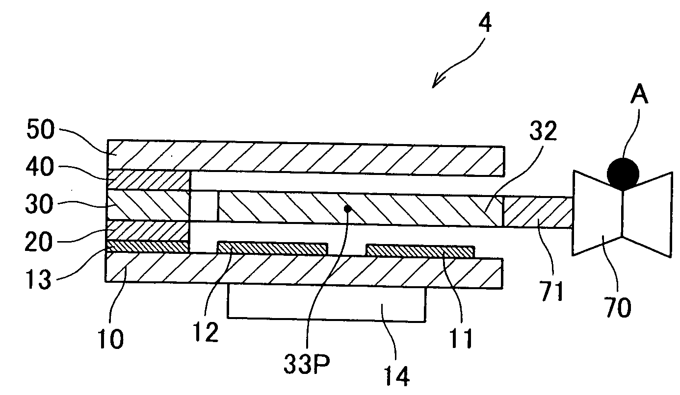
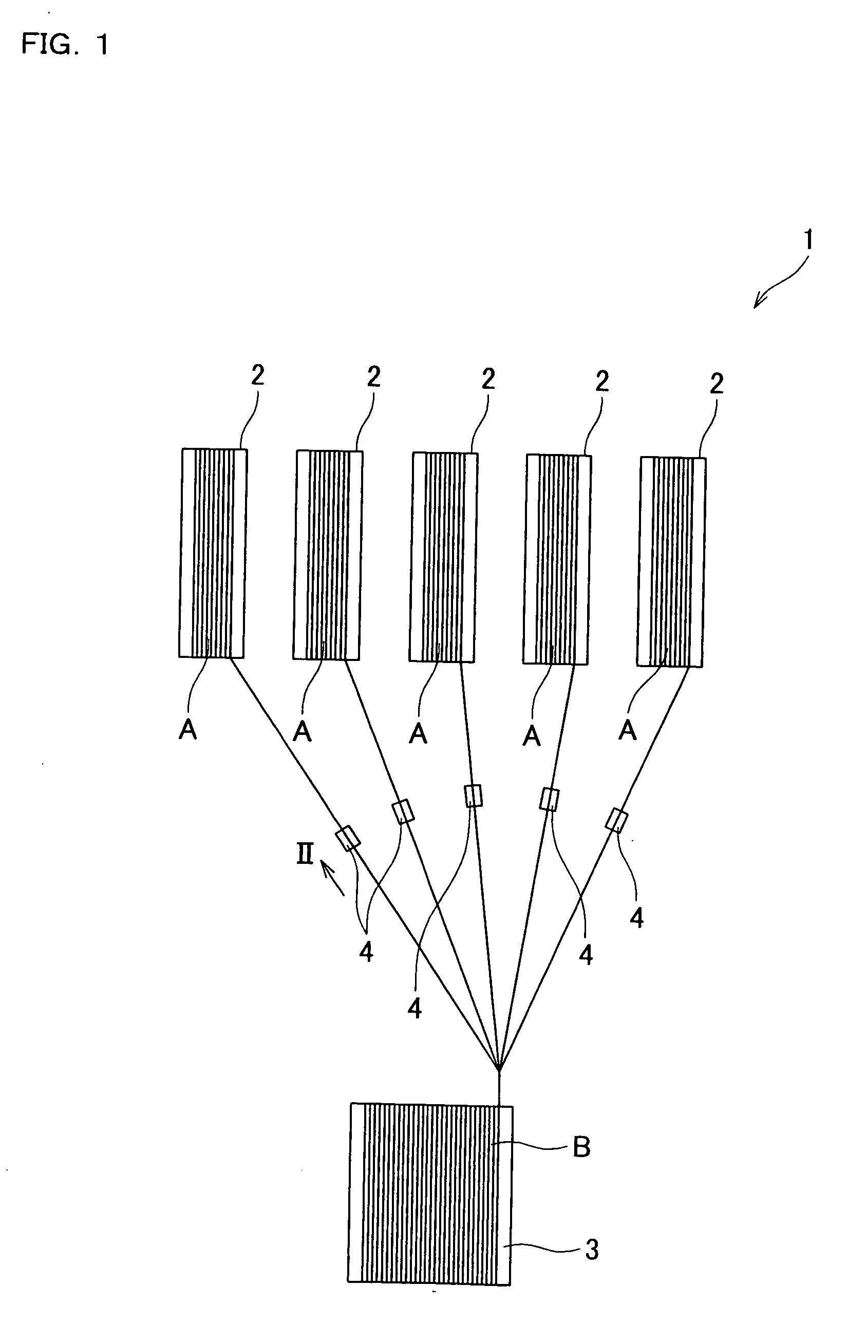
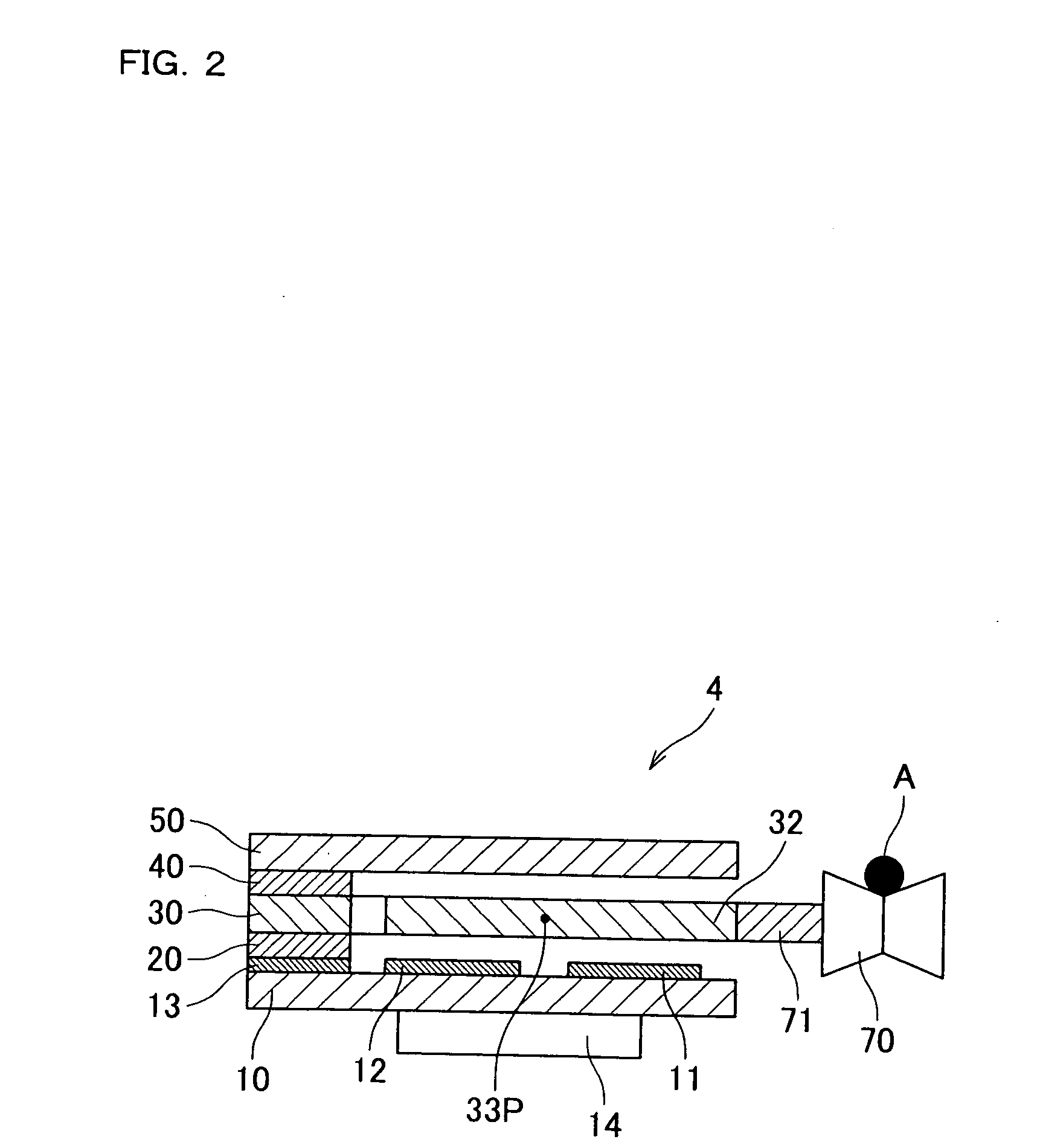
[0032]Hereinafter, preferred embodiments of the present invention will be described with reference to the accompanying drawings. FIG. 1 is a schematic view of a thread making machine including tension measuring apparatuses according to a first embodiment of the present invention.

[0033]As shown in FIG. 1, the thread making machine 1 includes a number of bobbins 2, a bobbin 3, and a number of tension measuring apparatuses 4. A fiber A is wound on each bobbin 2. The tension measuring apparatuses 4 are provided so as to correspond to the respective bobbins 2 to measure the magnitudes of the tensions of the fibers A drawn out from the respective bobbins 2.

[0034]In the thread making machine 1, the fibers A are drawn out from the respective bobbins 2 so as to uniformize the tensions measured by the tension measuring apparatuses 4. The drawn-out fibers A are bundled to make a thread B. The made thread B is wound on the bobbin 3. Afterward, the thread B wound on the bobbin 3 is processed by ...


PUM


Abstract

In a tension measuring apparatus, two fixed electrodes (11, 12) are distantly arranged on a single plane, and a movable electrode (32) is disposed parallel to the fixed electrodes to face the fixed electrodes. When a fiber (A) is pressed onto a force receiving portion (70), the movable electrode (32) is rotated around a rotational axis (33P). This changes the distances of the movable electrode (32) from the fixed electrodes (11, 12). The force received by the force receiving portion (70) from the fiber (A) is measured based on changes in the capacitance values of the capacitance elements (C11, C12) constituted by the movable electrode (32) and the respective fixed electrodes (11, 12).

Description

BACKGROUND OF THE INVENTION[0001]1. Field of the Invention[0002]The present invention relates to a tension measuring apparatus for measuring the magnitude of a force externally applied.[0003]2. Description of Related Art[0004]A force measuring apparatus is known for measuring the tension of a string or a wire. For example, Japanese Patent Unexamined Publication No. 2002-90239 discloses a tension detecting apparatus. In this apparatus, two distant points of a wire are hooked on attachment portions of the apparatus. The wire is hitched to a bent portion of the apparatus disposed between the two points of the wire. The bent portion perpendicularly protrudes beyond a straight line extending through the two points of the wire. In this state, the force applied to the bent portion is measured with a strain gauge to measure the tension of the wire.[0005]In the process of making a thread, a number of fibers must be bundled with keeping the tensions of the fibers uniform so that unevenness is...

Claims


Application Information

Patent Timeline
IPC IPC(8): G01N3/08
CPCG01L1/142G01L5/10G01L5/108
Inventor MORIMOTO, HIDEO
Owner NITTA CORP
Why Eureka
Try Eureka