Threading device of sewing machine

a threading device and sewing machine technology, applied in sewing apparatus, thin material handling, textiles and paper, etc., can solve the problems of reducing working efficiency, affecting the quality of sewing machine thread, and difficulty for users to visually check the amount of thread, so as to prevent time-wasting air supply operation, easy and visual recognition, and efficient feeding

Inactive Publication Date: 2008-10-23
JUKI CORP
View PDF5 Cites 18 Cited by
  • Summary
  • Abstract
  • Description
  • Claims
  • Application Information

AI Technical Summary

Benefits of technology

[0015]According to the first aspect of the invention, the thread inserting base includes the transparent member through which at least the joining portion of the thread path and the air path can be visually recognized from the outside of the sewing machine frame. Therefore, it is possible to easily and visually recognize whether the thread inserted from the thread inserting port is reached to a depth that is sufficient for the thread to be efficiently fed by the air discharged from the air path. Consequently, it is possible to prevent a time-wasting air supplying operation of the air supply device like in the background art in which the operator cannot visually recognize whether the thread is inserted to a sufficient depth from the thread inserting port or not. Thus, the threading work can be carried out easily and efficiently. Moreover, the illuminating means irradiates the joining portion of the thread path and the air path. Thus, it is possible to enhance visibility of the thread inserted from the thread inserting port.
[0016]In addition, in a case in where a plurality of thread inserting ports is provided, the thread inserting port into which the thread should be inserted can be shown to an operator by turning on the associated illuminating means. In such a ...

Problems solved by technology

Therefore, it is difficult for a user to visually check an amount of the thread inserted into a thread inserting port from the outer side of the sewing machine frame.
Accordingly, in the event that the amount of the thread inserted into the thread inserting port is insufficient, there is a problem that the compressed air cannot be sprayed directly toward the thread so that the thread cannot be fed smoothly even if the lever for the air pump is operated repetitively.
Consequently, there is a problem that the lev...

Method used


Image

  • Threading device of sewing machine
  • Threading device of sewing machine
  • Threading device of sewing machine

Examples


Embodiment Construction

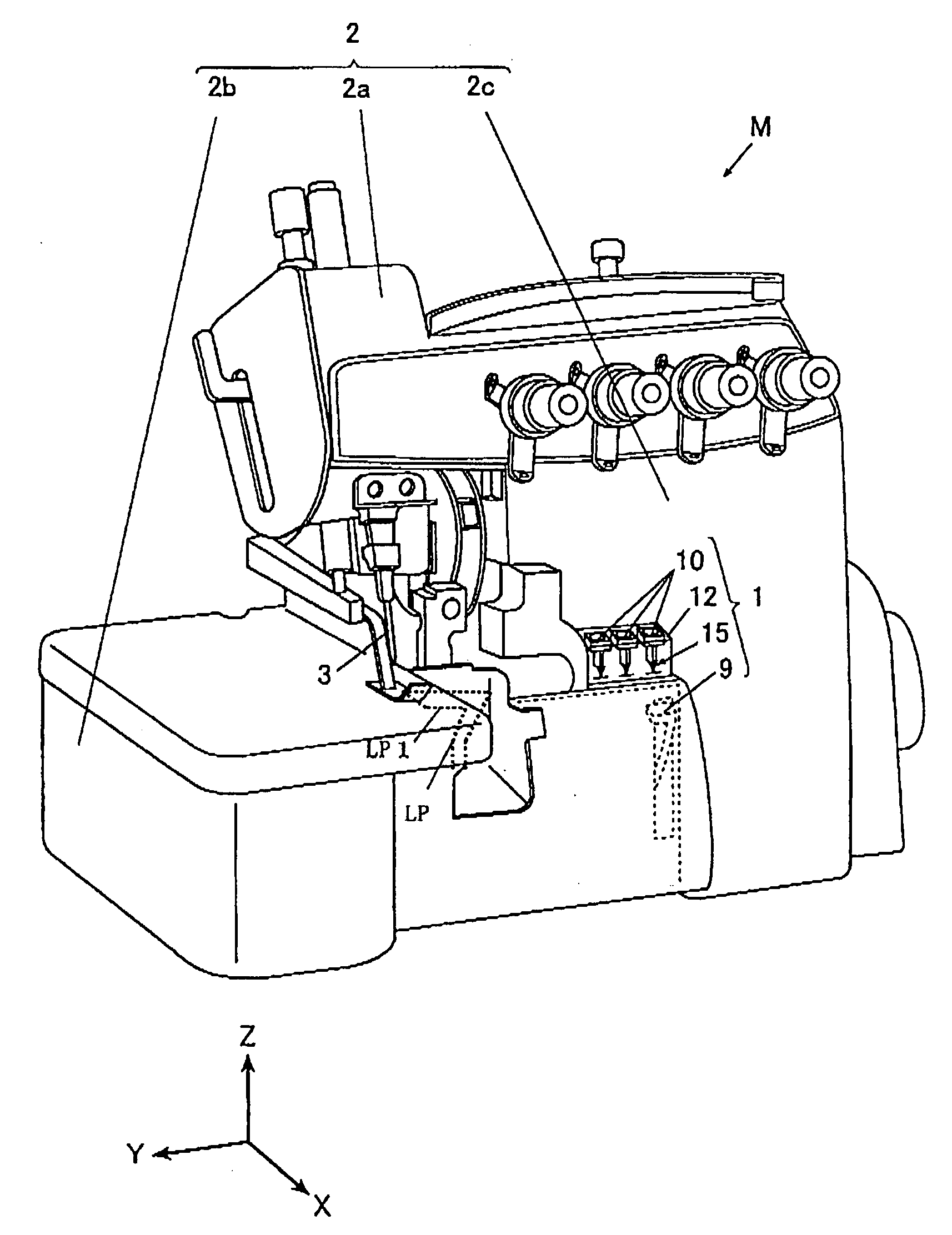
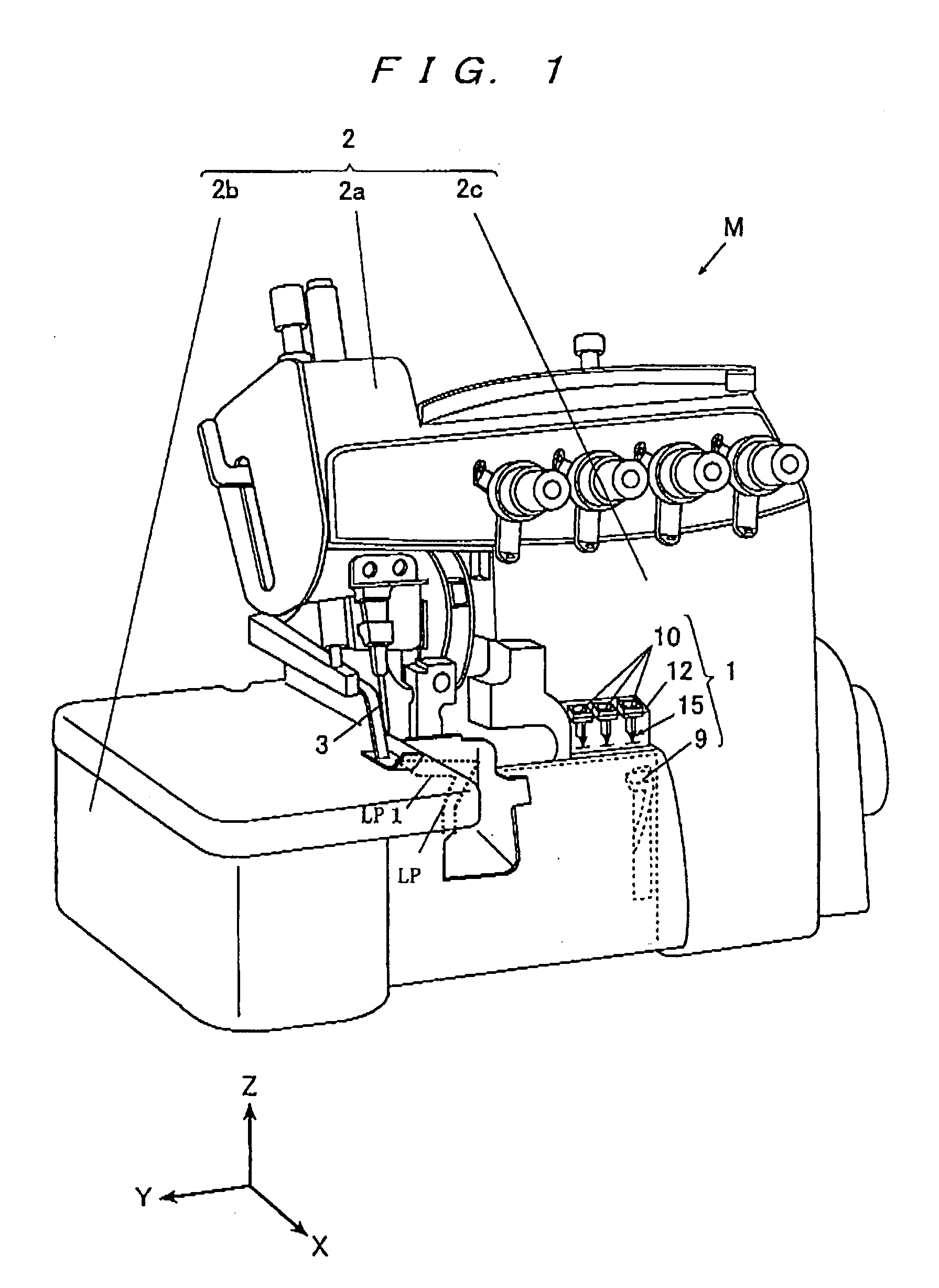
[0025]Hereinafter, exemplary embodiments of the invention will be explained with reference to FIGS. 1 to 4. The following exemplary embodiments and the drawings do not limit the scope of the invention. In the exemplary embodiments, directions of respective portions of a sewing machine M are defined by X, Y and Z axes shown in the drawings. In a state in which the sewing machine M is disposed on a horizontal plane, a Z-axis direction is a vertical direction (an up-and-down direction), a Y-axis direction is a longitudinal direction of an arm portion 2a (a right-and-left direction), and an X-axis is a front-and-rear direction which is horizontal and is orthogonal to the Y-axis direction.

(Overall Structure)

[0026]FIG. 1 is a schematic perspective view of the sewing machine M having a threading device 1 according to an exemplary embodiment.

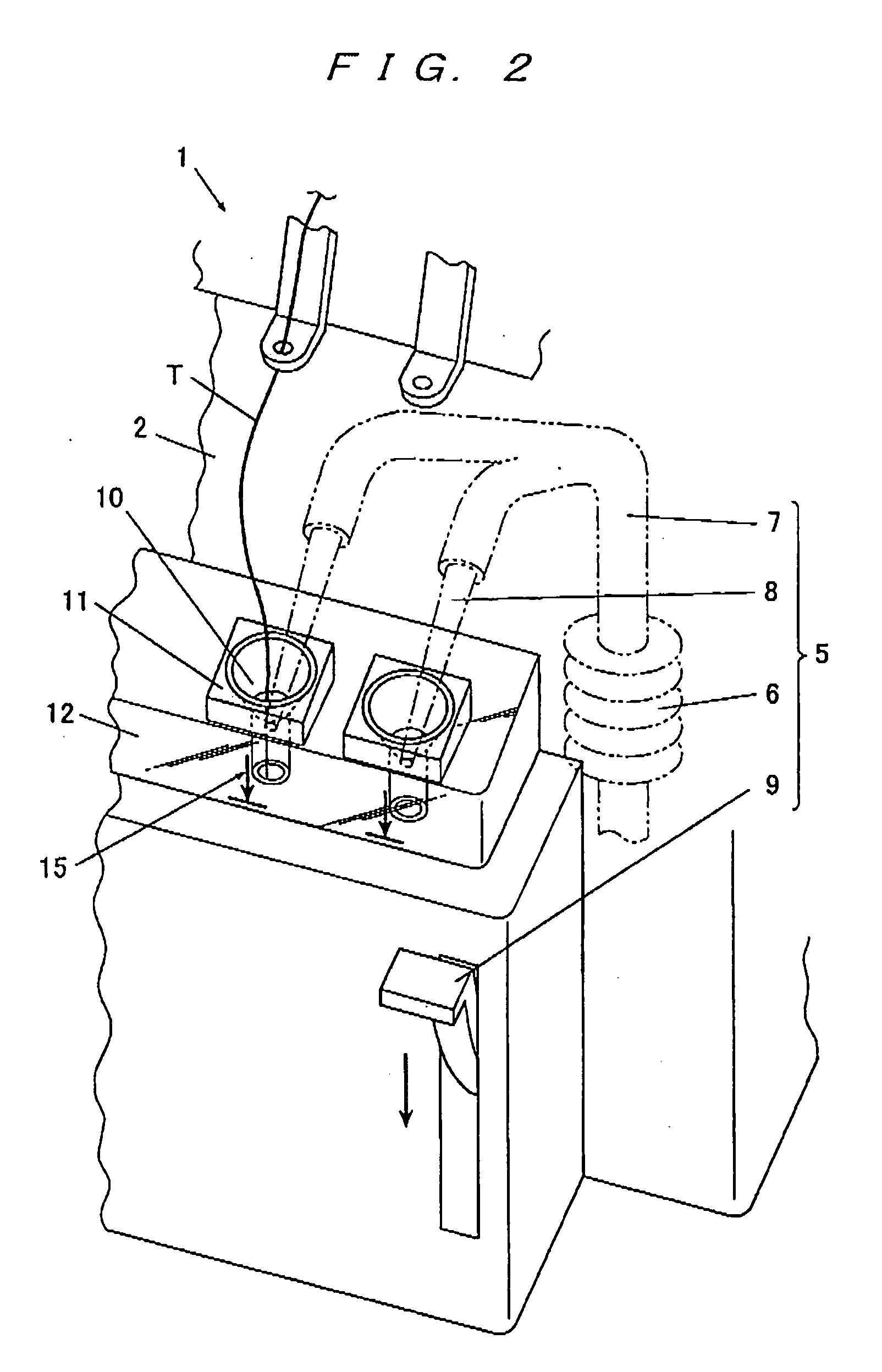
[0027]As shown in FIGS. 1 and 2, the threading device 1 includes a thread inserting base 12 formed with opening portions 10 opened toward an outer side...


PUM


Abstract

A threading device of a sewing machine includes a thread inserting base formed with a thread path hole having a thread inserting port opened toward an outer side of a sewing machine frame, and further formed with an air path hole which joins the thread path hole in the vicinity of the thread inserting port, an air supply device coupled to the air path hole to supply compressed air, and illuminating means provided on the sewing machine frame to irradiate a joining portion of the thread path hole and the air path hole. The thread inserting base includes a transparent member through which at least the joining portion of the thread path hole and the air path hole can be visually recognized.

Description

CROSS-REFERENCE TO RELATED APPLICATION[0001]The present application claims priority from Japanese Patent Application No. 2006-291333 filed on Oct. 26, 2006, the entire content of which is incorporated herein by reference.TECHNICAL FIELD[0002]The present invention relates to a threading device of a sewing machine which feeds a looper thread toward a looper by utilizing air.BACKGROUND ART[0003]A threading device of a sewing machine inserts a thread into a thread hole of a looper which forms a seam by cooperating with a needle. In the threading device, there is known a technique in which an opening portion is provided on an outer side of a sewing machine frame, and compressed air is sprayed toward an inner part of a threading tube which is a path for a thread to pass through an inner side of the sewing machine frame, whereby the thread is fed toward the looper (see, e.g., Japanese Patent No. 2865470).[0004]In this threading device, the air is compressed by an air pump interlockingly wi...

Claims


Application Information

Patent Timeline
IPC IPC(8): D05B87/00D05B79/00
CPCD05B81/00D05B87/02
Inventor SADASUE, KAZUYA
Owner JUKI CORP
Why Eureka
Try Eureka