
Method for producing hot dip plated steel sheet and apparatus for hot dip plating

a technology of hot dip plating and steel sheets, which is applied in the direction of liquid surface applicators, coatings, metallic material coating processes, etc., can solve the problems of inconvenient operation, inability to normally perform wiping operation, and difficulty in removing surface oxide films formed on the surface of the plating bath or maintaining the wiping nozzle, etc., to suppress the formation of oxide films, reduce oxygen concentration, and easy and visual recognition

Active Publication Date: 2017-03-21
NIPPON STEEL CORP
View PDF26 Cites 5 Cited by
  • Summary
  • Abstract
  • Description
  • Claims
  • Application Information

AI Technical Summary

Benefits of technology

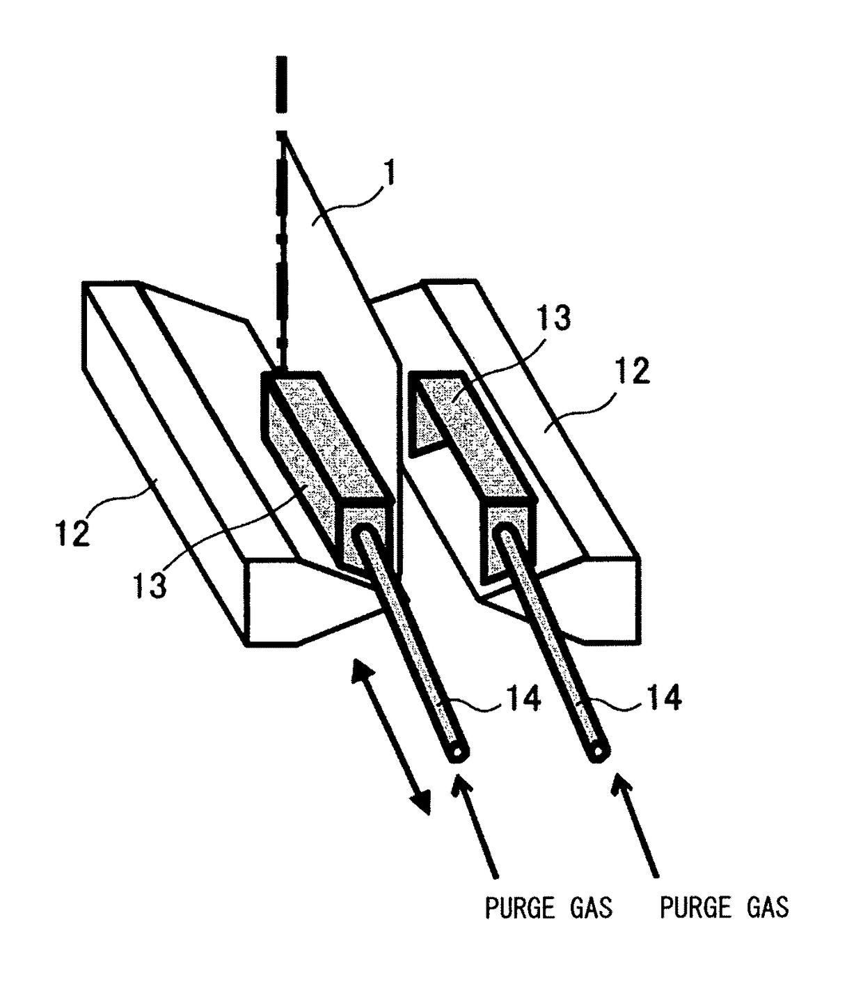
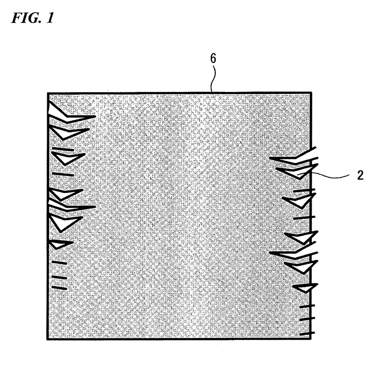
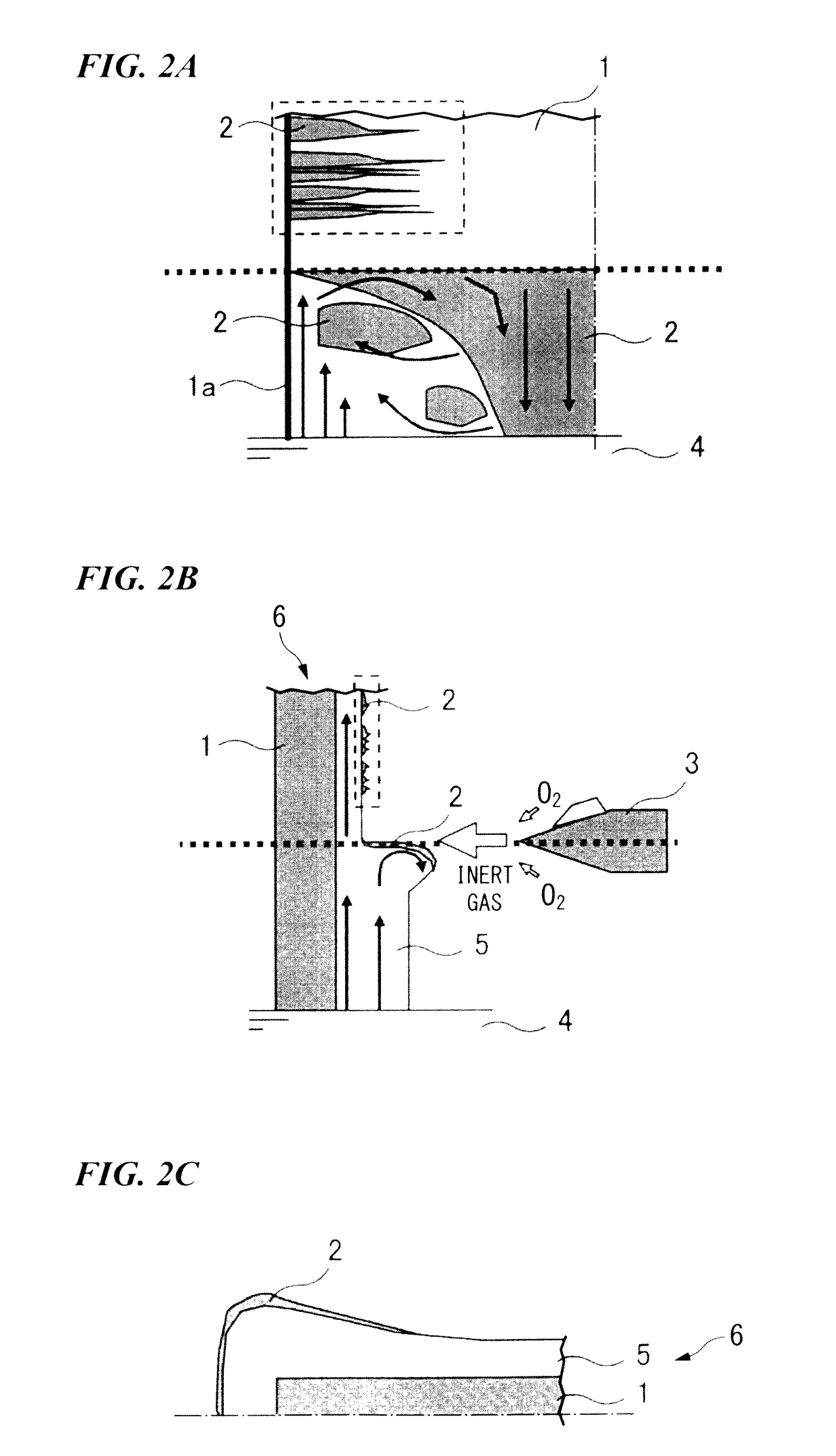
[0009]The inventors found that the oxide film formation position of the surface of the plated steel sheet is the gas injection position of steel sheet edge (end of the steel sheet) as a result of the repeated studies in order to solve the problems. Thus, the inventors decreased the oxygen concentration in the seal box by installing a seal box smaller than seal boxes of the conventional techniques so as to cover at least the steel sheet edge in the gas injection position where the coating weight is controlled. The inventors found that the formation of the oxide films in the surface of the plated steel sheet can be suppressed and the disadvantages in the operation and quality can be eliminated using this technique, and have contrived the present invention on the basis of this finding.
[0033]In the present invention, in the method for producing the hot dip plated steel sheet and the apparatus for the hot dip plating used in the method, it is possible to decrease the oxygen concentration in the seal box by installing a seal box smaller than seal boxes of the conventional techniques so as to cover at least the steel sheet edge in the gas injection position where the coating weight is controlled. According to the present invention, by means of the technique, it is possible to suppress the formation of the oxide films on the surface of the plated steel sheet and to easily and visually recognize the gas injection position for controlling the coating weight. In addition, it is easy to remove the surface oxide films formed on the surface of the plating bath or to maintain the wiping nozzle. Furthermore, according to the present invention, since it is possible to suppress the generation of zinc fume by the oxide films on the surface of the plating liquid, it is possible to ensure the quality of the plating by preventing metallic zinc from being adhered onto the apparatus such as the wiping nozzle. Thus, according to the present invention, it is possible to use the controlling technique of the coating weight for practical application so as to suppress the formation of the oxide films in the end of the plated steel sheet without degrading the operability and the plating quality.

Problems solved by technology

In addition, it is difficult to remove surface oxide films formed on the surface of the plating bath or to maintain the wiping nozzle.
For this reason, there is a problem in that the operation is inconvenient.
When metallic zinc is adhered to an apparatus such as the wiping nozzle due to the zinc fume, it is not possible to normally perform the wiping operation.
For this reason, there is a problem in that the quality of the product is degraded.
Accordingly, when the techniques are used in a practical application, there is a problem in that the operability and the plating quality are degraded.

Method used


Image

  • Method for producing hot dip plated steel sheet and apparatus for hot dip plating
  • Method for producing hot dip plated steel sheet and apparatus for hot dip plating
  • Method for producing hot dip plated steel sheet and apparatus for hot dip plating

Examples


first modified example of first embodiment

[0106]In the first embodiment of the present invention, one pair of seal boxes 13 and one pair of purge gas supply nozzles 14 are respectively provided in the both ends of steel sheets of the upper portion of the gas wiping nozzles 12, but two or more pairs of seal boxes and two or more pairs of purge gas supply nozzles may be provided therein. For example, in a first modified example of the first embodiment of the present invention, as shown in FIG. 7A, one pair (two pairs in total) of seal boxes 131 and one pair (two pairs in total) of purge gas supply nozzles 141 are respectively provided in the upper and lower portions of the gas wiping nozzle 12. Furthermore, FIG. 7B shows the gas sealing mechanism of the seal box according to the first modified example of the first embodiment.

[0107]As in the seal boxes 131 according to the modified example, when one pair of seal boxes 131 is respectively provided in both upper and lower portions of the gas wiping nozzle 12, it is possible to w...

second modified example of first embodiment

[0108]A second modified example of the first embodiment of the present invention shown in FIGS. 8A and 8B is different from the example of the first embodiment in that the shape of the seal box is different. A seal box 132 according to the modified example does not have a configuration in which the seal boxes are separately provided on both surface sides of the steel sheet 1 as in the first embodiment of the present invention, but is integrally formed in a shape (for example, substantially a U-shape) surrounding the steel sheet edge from the outside of the steel sheet edge. That is, the seal box 132 is provided so that the steel sheet 1 is interposed in the substantially U-shaped opening. In addition, as shown in FIG. 8B, a portion (the end of the opening surface) of the opening facing the steel sheet 1 is provided with a nozzle 132a which injects a curtain seal gas.

[0109]In addition, unlike the case of the first embodiment of the present invention, a purge gas supply nozzle 142 is ...

third modified example of first embodiment

[0111]A third modified example of the first embodiment of the present invention shown in FIGS. 9A and 9B is an example in which two seal boxes 132 according to the second modified example are integrally combined with each other so as to cover the upper and lower portions of the gas wiping nozzle 12. Since a seal box 133 according to the modified example exists in both upper and lower portions of the gas wiping nozzles 12 as in the first modified example, it is possible to widen the region requiring the control of the oxygen concentration in the vicinity of the position where the wiping gas collides with the steel sheet 1. For this reason, it is possible to further improve the advantage of suppressing the formation of the whisper-shaped oxide films compared with the case of the first embodiment of the present invention. In addition, it is thought that the installation of the seal box 133 according to the modified example is easier than that of the seal box 131 according to the first ...


PUM

PropertyMeasurementUnit
widthaaaaaaaaaa
distanceaaaaaaaaaa
widthaaaaaaaaaa

Abstract

A method for producing a hot dip plated steel sheet, the method controlling a coating weight by injecting a gas toward a surface of a steel sheet from a time when the steel sheet continuously immersed into a plating bath is pulled up from the plating bath to a time when plating metal adhered onto the surface of the steel sheet is solidified, the method includes: setting an oxygen concentration of a bath surface of the plating bath to be more than or equal to 0.05 vol % and less than or equal to 21 vol % when the gas is injected toward the surface of the steel sheet; and setting an oxygen concentration in a space of an end of the steel sheet at a position where the gas collides with the steel sheet pulled up from the plating bath to be more than or equal to 0.05 vol % and less than or equal to 3 vol % when the gas is injected toward the surface of the steel sheet.

Description

BACKGROUND OF THE INVENTION[0001]Field of the Invention[0002]The present invention relates to a method for producing a hot dip plated steel sheet and an apparatus for hot dip plating used in the method.[0003]The present application is a national stage application of International Application No. PCT / JP2009 / 005089, filed Oct. 1, 2009, which claims priority to Japanese Patent Application No. 2008-256208, filed on Oct. 1, 2008, the content of which is incorporated herein by reference in its entirety.[0004]Description of Related Art[0005]In a process of producing a hot dip plated steel sheet, a coating weight is controlled by injecting a gas from a wiping nozzle toward a steel sheet during a time when the moving steel sheet (steel strip) is continuously immersed into a plating bath, the steel sheet is pulled up from the plating bath, and then plating metal coated onto a surface of the steel sheet is solidified. At this time, oxide films (dross) are formed on the plated surface of the st...

Claims


Application Information

Patent Timeline
Patent Type & Authority Patents(United States)
IPC IPC(8): B05D1/18C23C2/06C23C2/18C23C2/12C23C2/20
CPCC23C2/18C23C2/06C23C2/12C23C2/20C23C2/16C23C2/40
Inventor OOHASHI, TOORUKAGEYAMA, MASATOUCHIDA, SATOSHIHAMAGUCHI, KATSUHIRO
Owner NIPPON STEEL CORP
Learn More