Pressure Container With Differential Vacuum Panels

a vacuum panel and pressure container technology, applied in the field of plastic containers, can solve the problems of partial evacuation of the container, distortion of the container, significant mechanical stress on the structure of the container, etc., and achieve the effects of reducing the weight of the container, improving the dent resistance and resistance to torsion displacement, and controlling the overall response to vacuum pressur

Active Publication Date: 2008-10-23
MELROSE DAVID MURRAY +1
View PDF63 Cites 75 Cited by
  • Summary
  • Abstract
  • Description
  • Claims
  • Application Information

AI Technical Summary

Benefits of technology

[0018]The present invention provides an improved blow molded plastic container, where a controlled deflection flex panel is placed on one sidewall of a container and a second controlled deflection flex panel having a different response to vacuum pressure is placed on an alternate sidewall. By way of example, a container having four controlled deflection flex panels may be disposed in two pairs on symmetrically opposing sidewalls, whereby one pair of controlled deflection flex panels responds to vacuum force at a different rate to an alternatively positioned pair. The pairs of controlled deflection flex panels may be positioned an equidistance from the central longitudinal axis of the container, or may be positioned at differing distances from the centerline of the container. In addition the design allows for a more controlled overall response to vacuum pressure and improved dent resistance and resistance to torsion displacement of post or land areas between the panels. Further, improved reduction in container weight is achieved, along with potential for development of squeezable container designs.
[0021]The vacuum panels may be selected so that they are highly efficient. See, e.g., PCT application NO. PCT / NZ00 / 00019 (Melrose) where panels with vacuum panel geometry are shown. ‘Prior art’ vacuum panels are generally flat or concave. The controlled deflection flex panel of Melrose of PCT / NZ00 / 00019 and the present invention is outwardly curved and can extract greater amounts of pressure. Each flex panel has at least two regions of differing outward curvature. The region that is less outwardly curved (i.e., the initiator region) reacts to changing pressure at a lower threshold than the region that is more outwardly curved. By providing an initiator portion, the control portion (i.e., the region that is more outwardly curved) reacts to pressure more readily than would normally happen. Vacuum pressure is thus reduced to a greater degree than prior art causing less stress to be applied to the container sidewalls. This increased venting of vacuum pressure allows for may design options: different panel shapes, especially outward curves; lighter weight containers; less failure under load; less panel area needed; different shape container bodies.
[0023]All sidewalls containing the controlled deflection flex panels may have one or more ribs located within them. The ribs can have either an outer or inner edge relative to the inside of the container. These ribs may occur as a series of parallel ribs. These ribs are parallel to each other and the base. The number of ribs within the series can be either an odd or even. The number, size and shape of ribs are symmetric to those in the opposing sidewall. Such symmetry enhances stability of the container.
[0025]The advanced highly efficient design of the controlled deflection panels of the first pair of panels more than compensates for the fact that they offer less surface area than the larger front and back panels. By providing for the first pair of panels to respond to lower thresholds of pressure, these panels may begin the function of vacuum compensation before the second larger panel set, despite being positioned further from the centerline. The second larger panel set may be constructed to move only minimally and relatively evenly in response to vacuum pressure, as even a small movement of these panels provides adequate vacuum compensation due to the increased surface area. The first set of controlled deflection flex panels may be constructed to invert and provide much of the vacuum compensation required by the package in order to prevent the larger set of panels from entering an inverted position. Employment of a thin-walled super light weight preform ensures that a high level of orientation and crystallinity are imparted to the entire package. This increased level of strength together with the rib structure and highly efficient vacuum panels provide the container with the ability to maintain function and shape on cool down, while at the same time utilizing minimum gram weight.
[0026]The arrangement of ribs and vacuum panels on adjacent sides within the area defined by upper and lower container bumpers allows the package to be further light weighted without loss of structural strength. The ribs are placed on the larger, non-inverting panels and the smaller inverting panels may be generally free of rib indentations and so are more suitable for embossing or debossing of Brand logos or name. This configuration optimizes geometric orientation of squeeze bottle arrangements, whereby the sides of the container are partially drawn inwardly as the main larger panels contract toward each other. Generally speaking, in prior art as the front and back panels are drawn inwardly under vacuum the sides are forced outwardly. In the present invention the side panels invert toward the centre and maintain this position without being forced outwardly beyond the post structures between the panels. Further, this configuration of ribs and vacuum panel represents a departure from tradition.

Problems solved by technology

Hot-fill applications impose significant and complex mechanical stress on a container structure due to thermal stress, hydraulic pressure upon filling and immediately after capping, and vacuum pressure as the fluid cools.
The hot fluid causes the container walls to soften and then shrink unevenly, further causing distortion of the container.
As the liquid, and the air headspace under the cap, subsequently cool, thermal contraction results in partial evacuation of the container.
The vacuum created by this cooling tends to mechanically deform the container walls.
The amount of “flex” available in each panel is limited, however, and as the limit is approached there is an increased amount of force that is transferred to the sidewalls.
This causes stress to be placed on the container side wall.
There is a forced outward movement of the heat panels, which can result in a barreling of the container.
With the panel being generally flat, however, the amount of movement is limited in both directions.
However, a container that is used for hot-fill applications is subject to additional mechanical stresses on the container that result in the container being more likely to fail during storage or handling.
For example, it has been found that the thin sidewalls of the container deform or collapse as the container is being filled with hot fluids.
However, the inward flexing of the panels caused by the hot-fill vacuum creates high stress points at the top and bottom edges of the vacuum panels, especially at the upper and lower corners of the panels.
These stress points weaken the portions of the sidewall near the edges of the panels, allowing the sidewall to collapse inwardly during handling of the container or when containers are stacked together.
In the case of non-round containers, this is more challenging due to the fact that the level of orientation and, therefore, crystallinity is inherently lower in the front and back than on the narrower sides.

Method used


Image

  • Pressure Container With Differential Vacuum Panels
  • Pressure Container With Differential Vacuum Panels
  • Pressure Container With Differential Vacuum Panels

Examples


Embodiment Construction

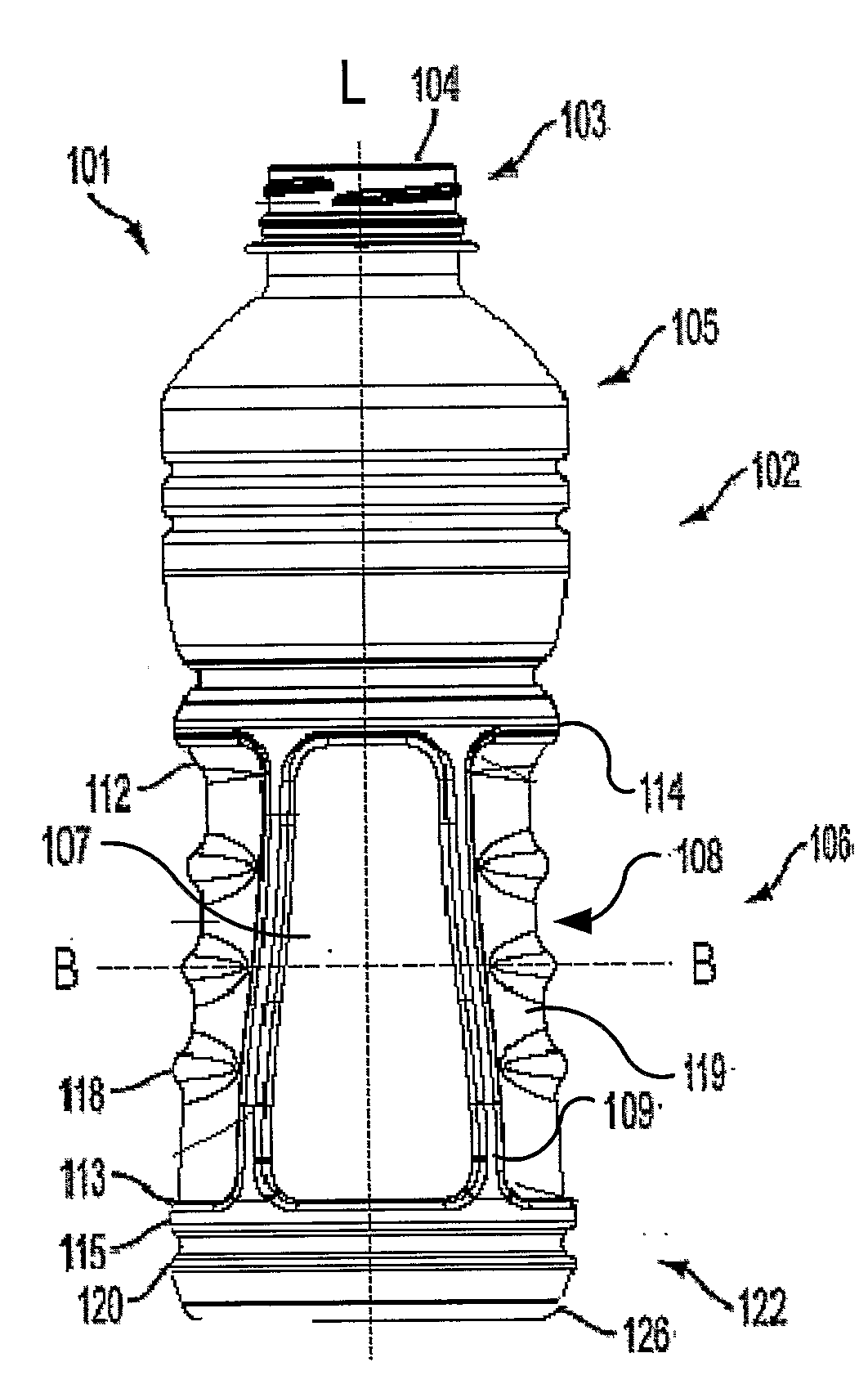
[0047]A thin-walled container in accordance with the present invention is intended to be filled with a liquid at a temperature above room temperature. According to the invention, a container may be formed from a plastic material such as polyethylene terephthlate (PET) or polyester. Preferably, the container is blow molded. The container can be filled by automated, high speed, hot-fill equipment known in the art.

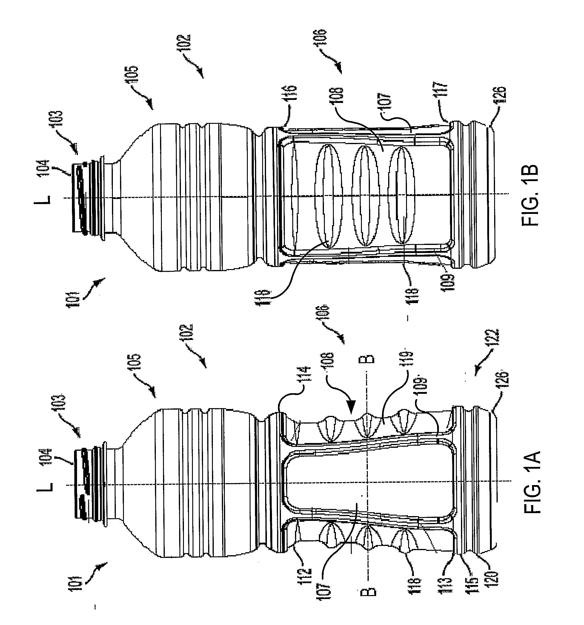
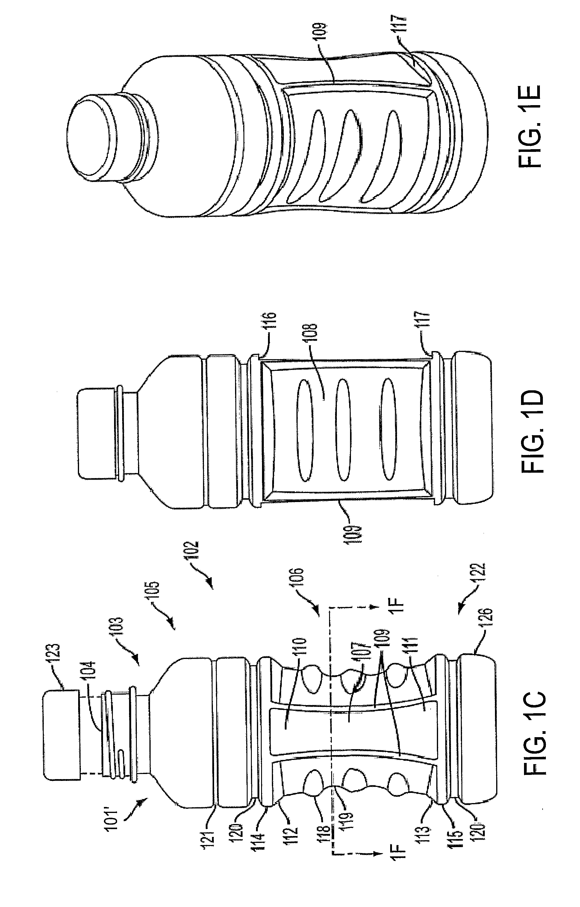
[0048]Referring now to the drawings, a first embodiment of the contained of the invention is indicated generally in FIGS. 1A and 1B, as generally having many of the well-known features of hot-fill bottles. The container 101, which is generally round or oval in shape, has a longitudinal axis L when the container is standing upright on its base 126. The container 101 comprises a threaded neck 103 for filling and dispensing fluid through an opening 104. Neck 103 also is sealable with a cap (not shown). The preferred container further comprises a roughly circular base 126 and a b...


PUM


Abstract

An improved blow molded plastic container having generally rounded sidewalls that are adapted for hot-fill applications has two adjacent sides and two pairs of controlled deflection panels, each pair reacting to vacuum pressure at differing rates of movement, whereby one pair inverts under vacuum pressure and the other pair remains available for increased squeezability or extreme vacuum extraction. The opposing sidewalls are symmetric relative to vacuum panel and rib shape and placement. The ribs and controlled deflection panels cooperate to retain container shape upon filling and cooling and also improves bumper denting resistance, decreases vacuum pressure within the container, and increases light weight capability.

Description

BACKGROUND OF THE INVENTION[0001]1. Field of the Invention[0002]The present invention relates generally to plastic containers, and more particularly to hot-fillable containers having collapse or vacuum panels.[0003]2. Statement of the Prior Art[0004]Hot-fill applications impose significant and complex mechanical stress on a container structure due to thermal stress, hydraulic pressure upon filling and immediately after capping, and vacuum pressure as the fluid cools.[0005]Thermal stress is applied to the walls of the container upon introduction of hot fluid. The hot fluid causes the container walls to soften and then shrink unevenly, further causing distortion of the container. The plastic walls of the container—typically made of polyester—may, thus, need to be heat-treated in order to induce molecular changes, which would result in a container that exhibits better thermal stability.[0006]Pressure and stress are acted upon the sidewalls of a heat resistant container during the filli...

Claims


Application Information

Patent Timeline
Patent Type & Authority Applications(United States)
IPC IPC(8): B65D90/02
CPCB65D1/0223B65D79/005B65D2501/0081B65D2501/0036B65D2501/0027B65D79/0084
Inventor MELROSE, DAVIDKELLEY, PAULBYSICK, SCOTTHOWELL, JUSTIN
Owner MELROSE DAVID MURRAY
Why Eureka
Try Eureka