System and method for manufacturing concrete blocks

a technology of concrete blocks and manufacturing methods, applied in the field of manufacturing concrete wall blocks, can solve the problems of waste of materials, limit the ability to create decorative front faces on blocks, and add additional production costs

Inactive Publication Date: 2008-10-23
MARSHALL CONCRETE
View PDF99 Cites 28 Cited by
  • Summary
  • Abstract
  • Description
  • Claims
  • Application Information

AI Technical Summary

Benefits of technology

[0016]The present invention addresses the need in the industry for a system and method of making a block having two or more adjacent decorative faces that may resemble natural stone or other decorative masonry element. In an embodiment, a system and method for manufacturing an uncured concrete block using the dry-cast manufacturing process includes a mold box having a pair of side walls, a pair of side plates, an open top side and an open bottom side defining a mold cavity. Division plates can span the mold cavity to define multiple mold cavities. One or more end liners are disposed within the mold cavity. Hydraulic cylinders located within the mold cavity are configured to move the end liners between a first position and a second position. The hydraulic cylinders may be connected to a tubing system and an electronically controlled pumping unit. The hydraulic cylinders move the end liners move from the first position to the second position before a concrete mixture is introduced into the mold. End liners can be provided with a three-dimensional textured face to provide a decorative face to a side surface of the concrete block formed in the mold. End liners can also provide blocks with a tapered face. Before the block is stripped from the mold, the end liners are returned to the first position, so that the side surfaces are not damaged as the block is released.

Problems solved by technology

The need to eject the formed blocks through the bottom of the mold used in dry cast manufacture places limitations on the ability to create a decorative front face on the block because the sidewalls of the mold shear across the side surfaces of the block when stripped from the mold.
Splitting, however, adds additional production costs by requiring an additional step to the manufacturing process and results in waste material.
Furthermore, split-faced concrete blocks do not sufficiently resemble natural stone to satisfy some consumer needs.
However, the block produced from this method still does not satisfactorily resemble natural stone.
These methods, however, are labor intensive and can damage the blocks, resulting in a higher overall cost of production.
This process, however, limits the ability to provide for sidewalls that deviate from conformance to the smooth vertical sidewalls of the mold box because the downward movement of the block through the mold prevents a mold with stationary angled sidewalls or relief from being used.
However, this system does not teach the ability to impart a complex decorative face on the side surfaces of the blocks.
In addition, the mold must be taken apart to a degree that makes it difficult to perform maintenance or repairs of the biasing mechanisms.
This difficulty can cause undesirable delays in production.
A drawback, however, is that the core puller mechanism is a large and complex piece of machinery that requires a large amount of space on the production floor and can take a significant amount of time to setup and install.
Additionally, the moving parts in the mold may sometimes lack sufficient stability during various stages of molding, thereby causing undesired cracking of the block.

Method used


Image

  • System and method for manufacturing concrete blocks
  • System and method for manufacturing concrete blocks
  • System and method for manufacturing concrete blocks

Examples


Embodiment Construction

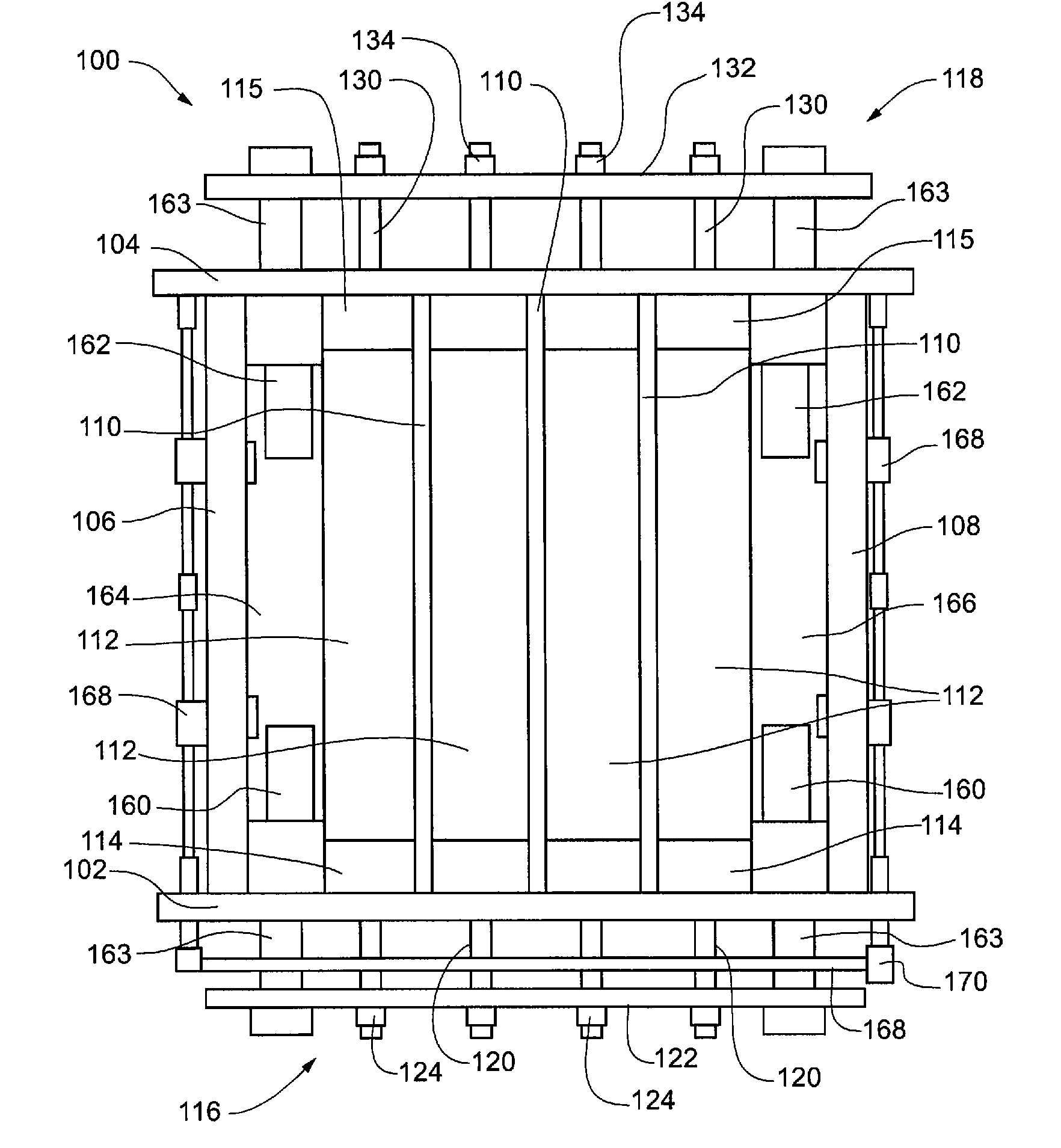
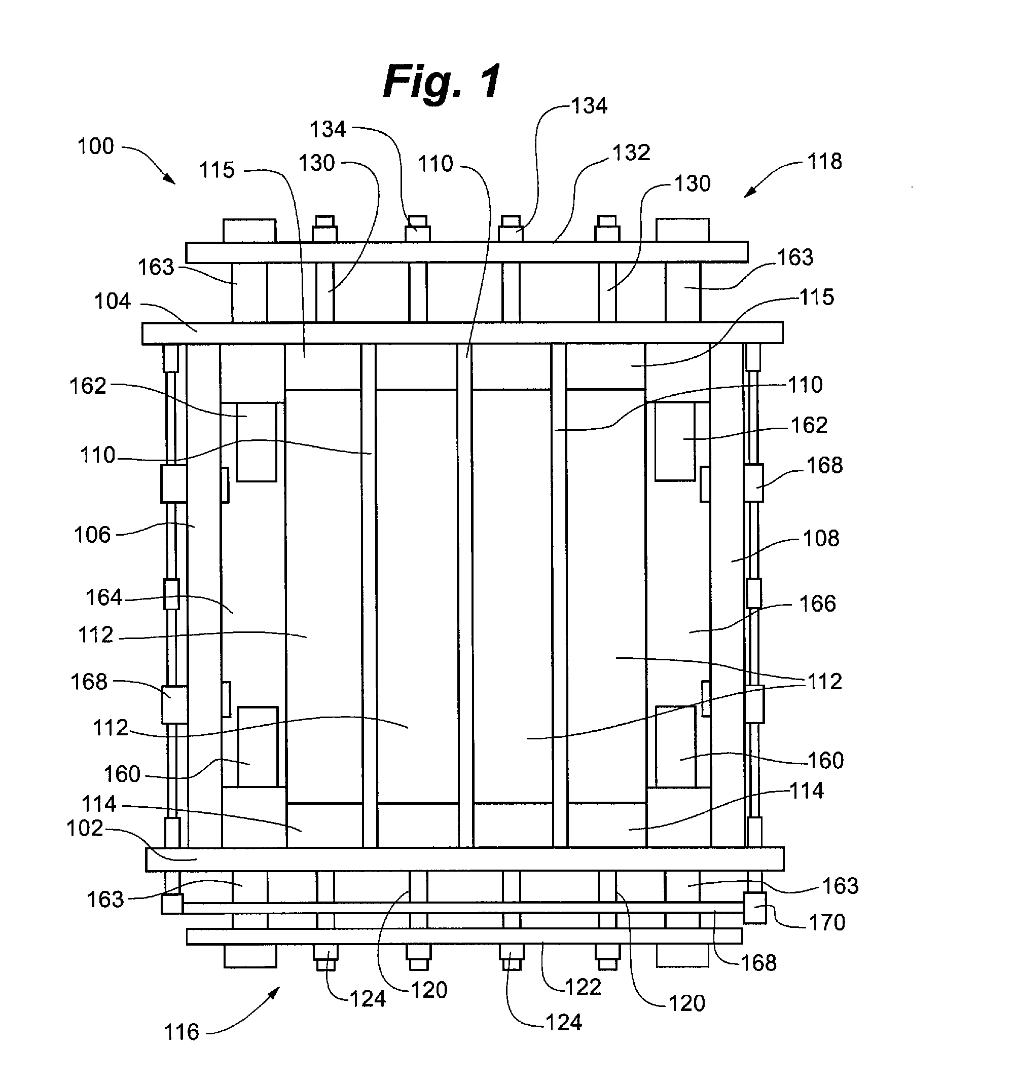
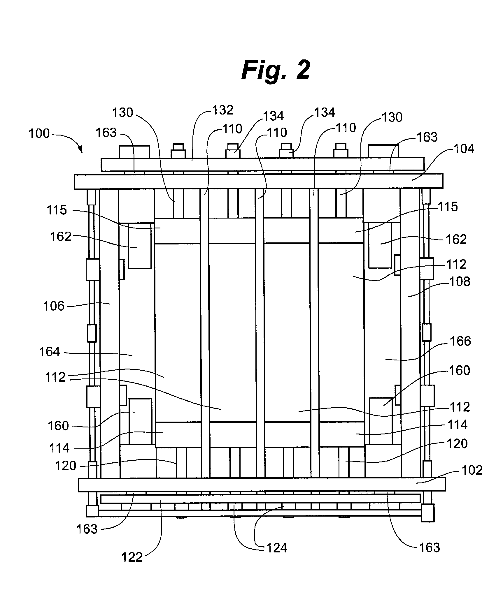
[0027]Referring to FIGS. 1-2, there is depicted a dry-cast block mold 100 according to an embodiment of the present invention. FIG. 1 depicts block mold 100 in a first position corresponding to a “release” or “strip” position. FIG. 2 depicts block mold 100 in a second position corresponding to a “fill” position.

[0028]Dry-cast block mold 100 generally includes of a pair of side bars 102, 104, and a pair of side plates 106, 108 that define an open interior region. Division plates 110 span side bars 102, 104, creating multiple mold cavities 112. A front end liner 114 and a rear end liner 115 can be disposed in each mold cavity 112. One of skill in the art will recognize that the number of division plates may be varied to increase or decrease the number of mold cavities, and accordingly, the respective number of end liners.

[0029]Front end liners 114 are connected and controlled by a front end liner connector assembly 116. Front end liners 114 are each connected to a front end liner push...


PUM

PropertyMeasurementUnit
heightaaaaaaaaaa
rate of speedaaaaaaaaaa
pressureaaaaaaaaaa

Abstract

A system and method for manufacturing an uncured concrete block using the dry-cast manufacturing process includes a mold box having a pair of side walls, a pair of side plates, an open top side and an open bottom side defining a mold cavity. One or more end liners are disposed within the mold cavity and are selectively shiftable within the mold cavity with hydraulic cylinders between a first position and a second position. The end liners can be provided with a three-dimensional textured face to impart a decorative face to a side surface of the concrete block formed in the mold or can also provide blocks with a tapered face when disposed in the second position while the mold is filled with concrete. Before the block is stripped from the mold, the end liners are returned to the first position, so that the side surfaces are not damaged as the block is released.

Description

FIELD OF THE INVENTION[0001]The present invention relates generally to the manufacture of concrete wall blocks. More specifically, the present invention relates to the manufacture of concrete wall blocks using the dry-cast method wherein the blocks have two or more adjacent decorative faces.BACKGROUND OF THE INVENTION[0002]Concrete blocks are used to form free standing and retaining walls. In such applications, the visible face or faces of the blocks are often provided with a textured or decorative appearance. Concrete blocks for forming walls are used in a variety of applications from small gardening applications to large-scale construction projects. Blocks are stacked in horizontal rows called courses. Multiple successive courses may be used to create a vertically rising wall of a desired height.[0003]The concrete blocks used in constructing such walls are often manufactured using the dry cast process, which uses dry-cast block machinery to form blocks at a relatively high rate of...

Claims


Application Information

Patent Timeline
Patent Type & Authority Applications(United States)
IPC IPC(8): B28B11/08
CPCB28B7/0041B28B7/0064B28B7/24B28B7/38B28B15/005
Inventor KLETTENBERG, CHARLES N.
Owner MARSHALL CONCRETE
Why Eureka
Try Eureka