Multimode power module

a power module and multi-mode technology, applied in the direction of electrochemical generators, secondary cell servicing/maintenance, transportation and packaging, etc., can solve the problems of low power efficiency transfer, disadvantageous significance of switching power loss relative to overall power, power loss associated with ppt switching, etc., to achieve the effect of maximizing output power, low power efficiency, and high power transfer efficiency

Active Publication Date: 2008-10-23
THE AEROSPACE CORPORATION
View PDF2 Cites 22 Cited by
  • Summary
  • Abstract
  • Description
  • Claims
  • Application Information

AI Technical Summary

Benefits of technology

[0009]An object of the invention is to provide a multimode power system with reduced switching and overhead losses during direct energy transfer.
[0011]Yet another object of the invention is to provide a multimode power system with reduced component count.
[0015]The present invention is a multimode power system that automatically selects one of the multiple operating modes to maximize output power when an attached battery is not fully charged. The system normally operates through direct energy transfer (DET) or peak power tracking (PPT). The system automatically switches between DET, boost PPT, and buck PPT modes. During the DET, the system connects a source, which may be a solar array, to an output, which may include a battery and a load, for high power transfer efficiency. The system extracts a maximum source power over a limited range of operating conditions. During PPT, the system adjusts the power transfer to varying conditions for maximum source power but the power transfer efficiency is lower than the DET due to switching and controller losses. Multimode power module automatically selects DET or PPT to continuously maximize output power to the battery and load. Low power systems such as miniature satellites particularly benefit from this the multimode power selection method because power losses associated with PPT are significantly reduced relative to overall power.

Problems solved by technology

Peak power tracking (PPT) mode is used during high and low array voltages in response to varying temperature and illumination conditions for maximum source power but power efficiency transfer is lower due to switching and controller losses.
Power modules have been used on miniature satellites but suffer from power losses associated with PPT switching.
Switching power losses are disadvantageously significant relative to overall power.
However, maximum source power is not continuously extracted by this DET method because array voltage is equal to varying battery voltage.
The influence of array temperature and degradation to power generation is neglected.
However, power dissipation is significant because the switching converter and control circuit are continuously active.
However, the system is designed specifically for motors and is not directly applicable to other systems such as solar power.
The converter disadvantageously has an excessive component count.
Converters are supplied in compact packages but are unsuitable of DET.
Existing power modules disadvantageously suffer from PPT switching losses, excessive component count, exclusive continuous high power operation without entering standby modes, and stand alone connections between a power source and loads.

Method used


Image

  • Multimode power module
  • Multimode power module
  • Multimode power module

Examples


Embodiment Construction

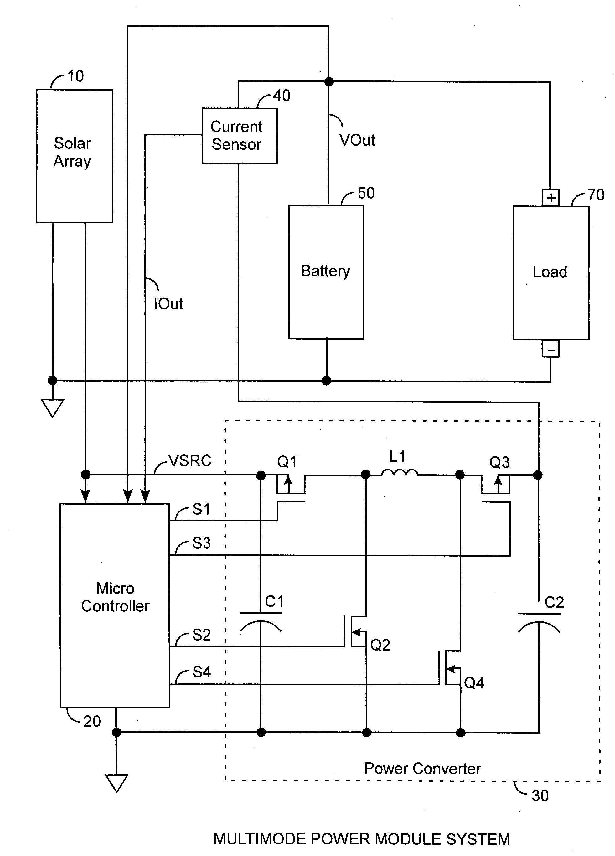
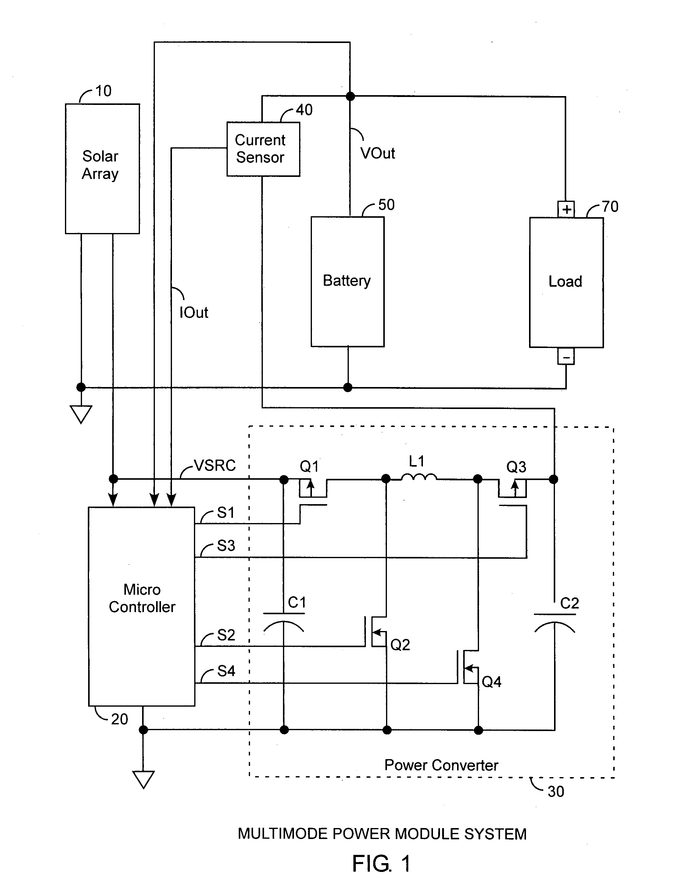
[0021]An embodiment of the invention is described with reference to the figures using reference designations as shown in the figures. Referring to FIG. 1, a multimode power module system is used to transfer power from a source 10, such as a solar array, under power transfer control of a microcontroller 20 using a power converter 30 and a current sensor 40. The power transfer is from the array 10 to an output that typically includes a battery 50 and a load 70. The power converter 30 provides an output voltage VOut that passes through current sensor 40 to the battery 50 and load 70. The source voltage VSRC and the output voltage VOut and the output current IOut are sensed by the microcontroller 20. The output current and output voltage determine output power delivered to the battery 50 and load 70.

[0022]The microcontroller 20 provides under process control, four switch output signals S1, S2, S3, and S4 that are respectively connected to, and used to turn on and off, four switching tra...


PUM

PropertyMeasurementUnit
load voltageaaaaaaaaaa
output voltageaaaaaaaaaa
source voltageaaaaaaaaaa

Abstract

A multimode power module system automatically selects one of multiple operating modes to maximize power transfer in varying conditions by using direct energy transfer, boost peak power tracking, buck peak power tracking, charge limit, and eclipse standby modes with reduced switching losses, reduced component count, and scalability through connections of multiple power modules system.

Description

FIELD OF THE INVENTION[0001]The invention relates to the field of power supplies and battery chargers. More particularly, the present invention relates to multimode battery charging power modules for efficient energy transfer from solar cells to a battery.BACKGROUND OF THE INVENTION[0002]Power modules on space system have long been used to charge onboard batteries and provide power to system loads. Referring to FIG. 2, the power transfer from an array of solar cells to a battery is a function of temperature and sunlight illumination. The temperature is shown to have a range between 95° C. degrees to 15° C. degrees, having a nominal temperature of 55° C. degrees. A battery can be charged in three power modes including direct energy transfer (DET), boost peak power tracking (PPT), and buck PPT. During the DET mode, the power module connects source array to the battery and load for high efficiency. Peak power tracking (PPT) mode is used during high and low array voltages in response to...

Claims


Application Information

Patent Timeline
Patent Type & Authority Applications(United States)
IPC IPC(8): H01M10/44H01L31/058H02J7/00H02M1/00
CPCH01L31/02021H01M10/44Y02E10/50H02J7/35H01M10/465Y02E60/10
Inventor CALDWELL, DAVID J.CARIAN, PETER J.WILLHOFF, MICHAEL A.
Owner THE AEROSPACE CORPORATION
Why Eureka
Try Eureka