Fan apparatus

a technology of fan and fan body, which is applied in the direction of positive displacement liquid engine, piston pump, liquid fuel engine, etc., can solve the problem of large amount of heat generated by electronic components, and achieve the effect of increasing the static pressur

Active Publication Date: 2008-10-23
NIPPON DENSAN CORP
View PDF14 Cites 34 Cited by
  • Summary
  • Abstract
  • Description
  • Claims
  • Application Information

AI Technical Summary

Benefits of technology

[0011]With the above-described configuration, the air discharged by the fan apparatus can be substantially straightened, so that the air flow and the static pressure can be increased.

Problems solved by technology

In the blade server, electronic components are mounted in a high-density fashion, and a large amount of heat is generated by these electronic components.

Method used


Image

  • Fan apparatus
  • Fan apparatus
  • Fan apparatus

Examples


Embodiment Construction

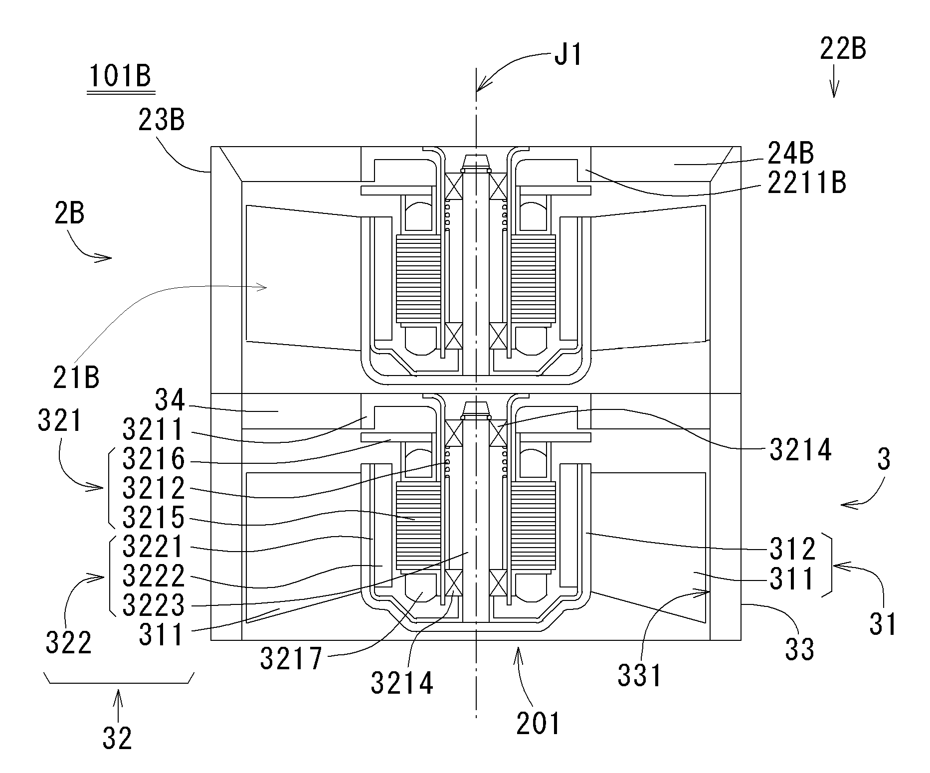
[0028]Referring to FIGS. 1 through 12, preferred embodiments of the present invention will be described in detail. It should be noted that in the explanation of the preferred embodiments of the present invention, when positional relationships and orientations of the different components are described as being up / down or left / right, ultimately positional relationships and orientations that are in the drawings are indicated. Positional relationships and orientations of the components after they have been assembled into an actual device are not indicated. In the following description, an axial direction indicates a direction substantially parallel to a rotation axis, and a radial direction indicates a direction substantially perpendicular to the rotation axis.

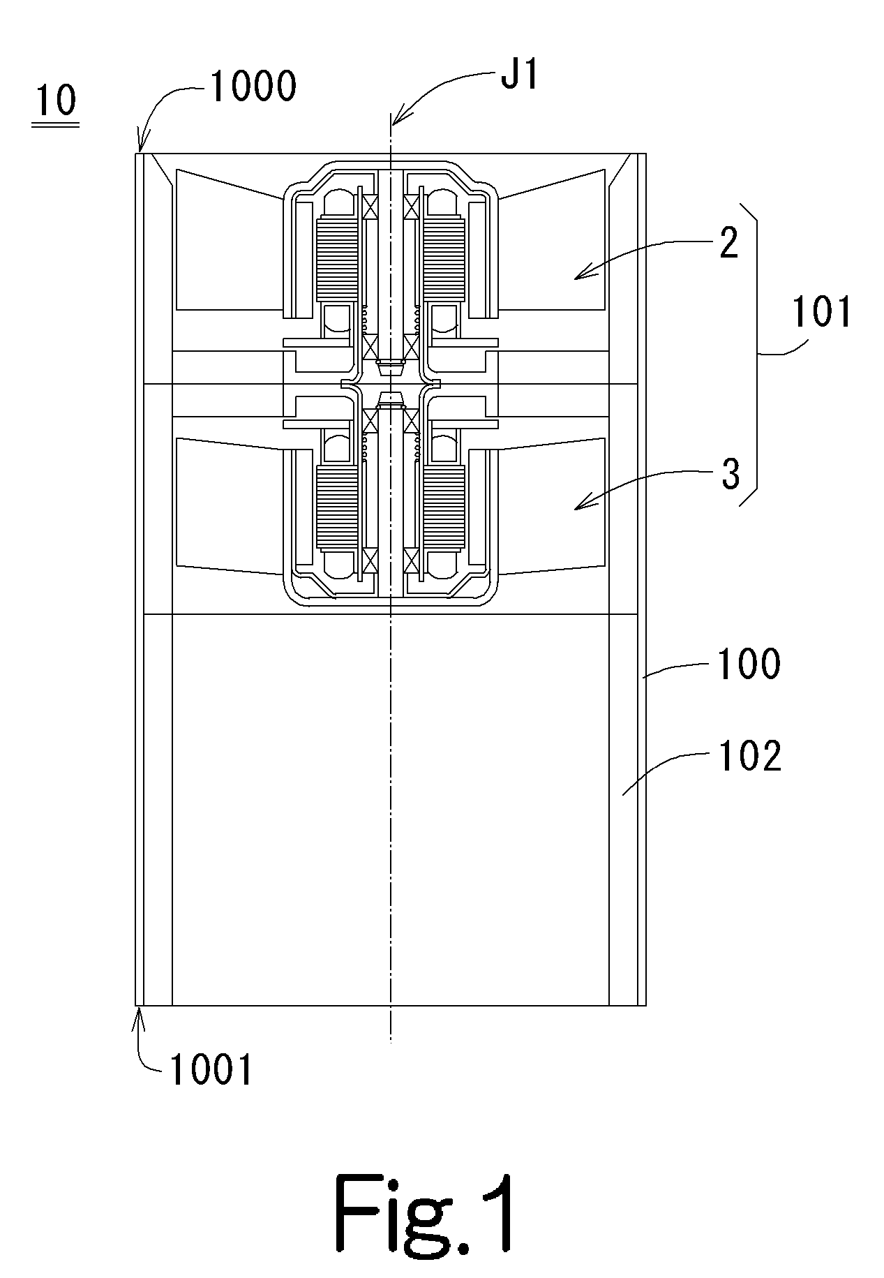
[0029]First, the configuration of a fan apparatus 10 of the first preferred embodiment of the present invention will be described. FIG. 1 is a sectional view showing the fan apparatus of the first preferred embodiment of the prese...


PUM


Abstract

A fan apparatus includes a casing and a fan unit. The casing is a hollow member having an inlet and an outlet. The fan unit has an inlet and an outlet, and includes a plurality of axial fans. The fan unit is disposed on the inside of the casing, and the inlet of the fan unit is disposed in the vicinity of the inlet of the casing. The position of the fan unit within the casing can be varied in order to alter the air flow and static pressure of the air discharged by the fan apparatus.

Description

BACKGROUND OF THE INVENTION[0001]1. Field of the Invention[0002]The present invention relates to a fan apparatus, and particularly to a fan apparatus including a fan unit and a casing in which the fan unit is disposed.[0003]2. Description of the Related Art[0004]As one type of server, there is a blade server. The blade server is a computer system provided with one or more circuit boards called server blades. The server blades include electronic components such as an MPU (Micro Processing Unit), a memory, and / or a hard disk mounted thereon.[0005]Each server blade is included in a chassis. The chassis is arranged in a rack cabinet. An example in which server blades are disposed in a chassis is shown in JP-A-2004-240967, for example.[0006]In the blade server, electronic components are mounted in a high-density fashion, and a large amount of heat is generated by these electronic components. The heat that is generated by the components is likely to remain in the chassis. In order to radi...

Claims


Application Information

Patent Timeline
Patent Type & Authority Applications(United States)
IPC IPC(8): F01D1/10F04D29/52F04D13/06
CPCF04D19/007F04D25/0613F04D29/526
Inventor HAYASHIGAITO, TOMOIWAMOTO, KENJIKATO, YOSHIHISANISHIDA, HIRONOBUYAMADA, SUGURUMIYAKODA, MANABU
Owner NIPPON DENSAN CORP
Why Eureka
Try Eureka