
Meat tenderizing machine and method of use

a meat tenderizing machine and meat technology, applied in meat tenderising, piercing-based meat tenderising, butchering and other directions, can solve the problems of danger to the hand of the operator, and inability to handle thick pieces, etc., to achieve fast and efficient manner

Inactive Publication Date: 2008-10-23
LUMAR IDEAL II
View PDF7 Cites 5 Cited by
  • Summary
  • Abstract
  • Description
  • Claims
  • Application Information

AI Technical Summary

Benefits of technology

[0003]It is a feature of the present invention to provide a meat tenderizing machine which substantially overcomes the above-mentioned disadvantages of the prior art and which permits an operator person to tenderize large and thick pieces of meat with the hands of the operator being safely disposed and engaged away from the block of cutting blades.

Problems solved by technology

Such machines usually can handle only small pieces of meat and also cannot handle thick pieces and are dangerous to the operator's fingers.
A disadvantage of such a machine is that it can only handle small pieces of meat which is movable in a single plane only and there is also danger to the hand of an operator which is required to displace the sliding board with the meat thereon in the vicinity of the block of cutting blades.
Also, this machine is extremely slow in operation and can only handle pieces of meat which are no wider than the board's width or of the block of cutting blades.
Further, if the meat piece is repositioned to try and tenderize portions not penetrated by the blades, then the piece of meat is not uniformly tenderized.
There is the risk that the operator could use one hand to actuate the block of blades and the other hand to displace the piece of meat under the block thereby placing his hand in danger of being cut by the blades.

Method used


Image

  • Meat tenderizing machine and method of use
  • Meat tenderizing machine and method of use
  • Meat tenderizing machine and method of use

Examples


Embodiment Construction

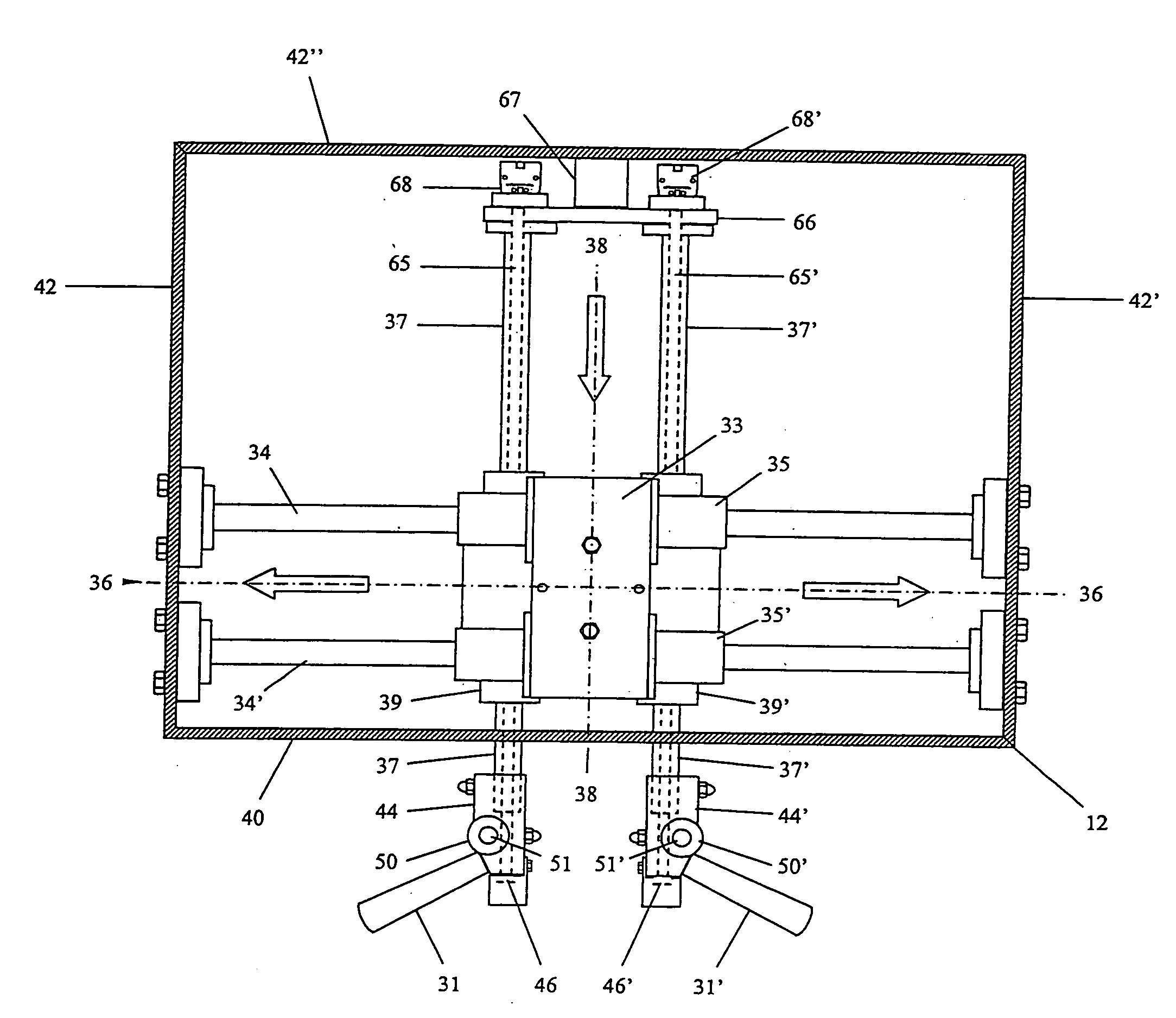
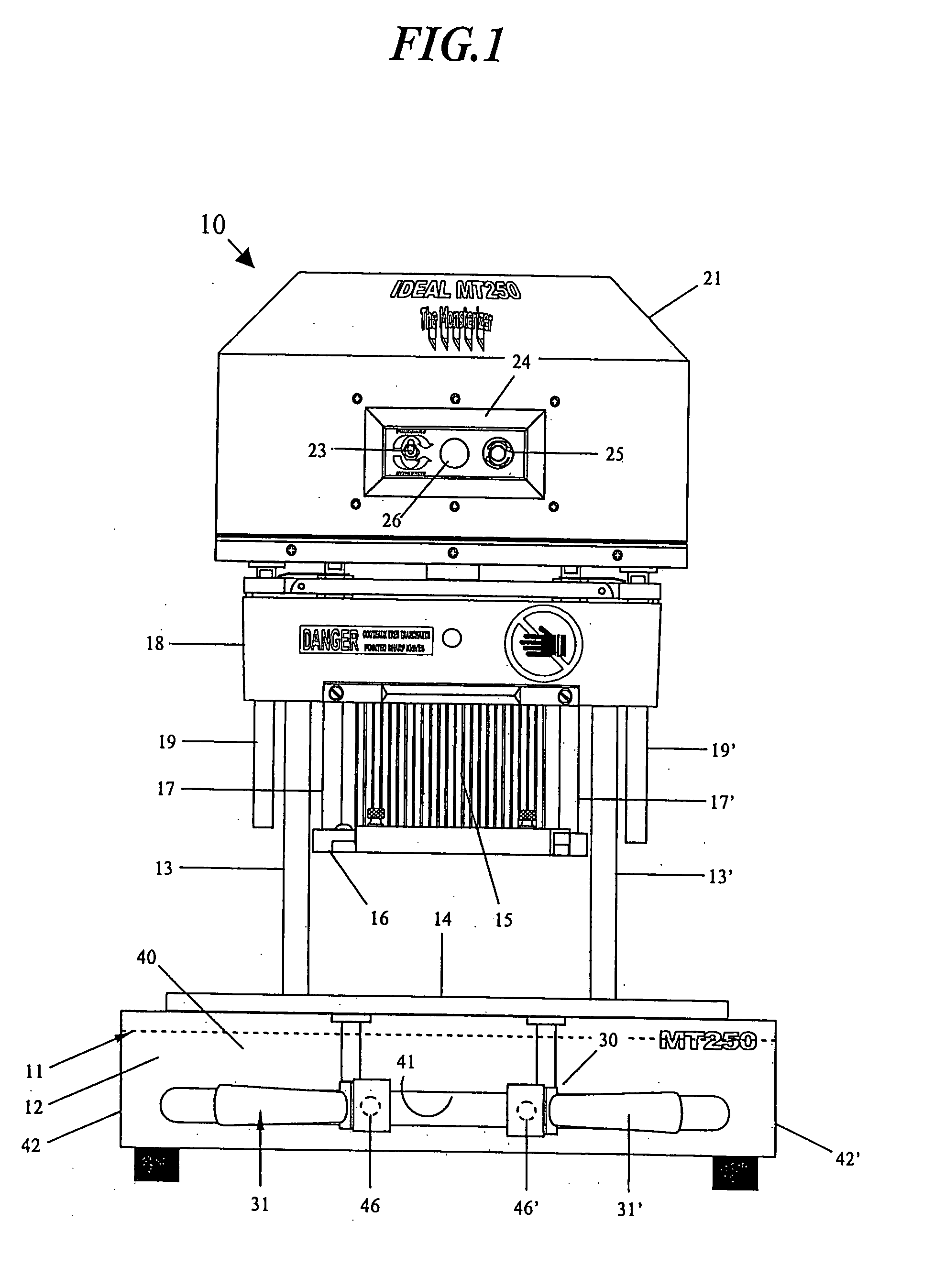
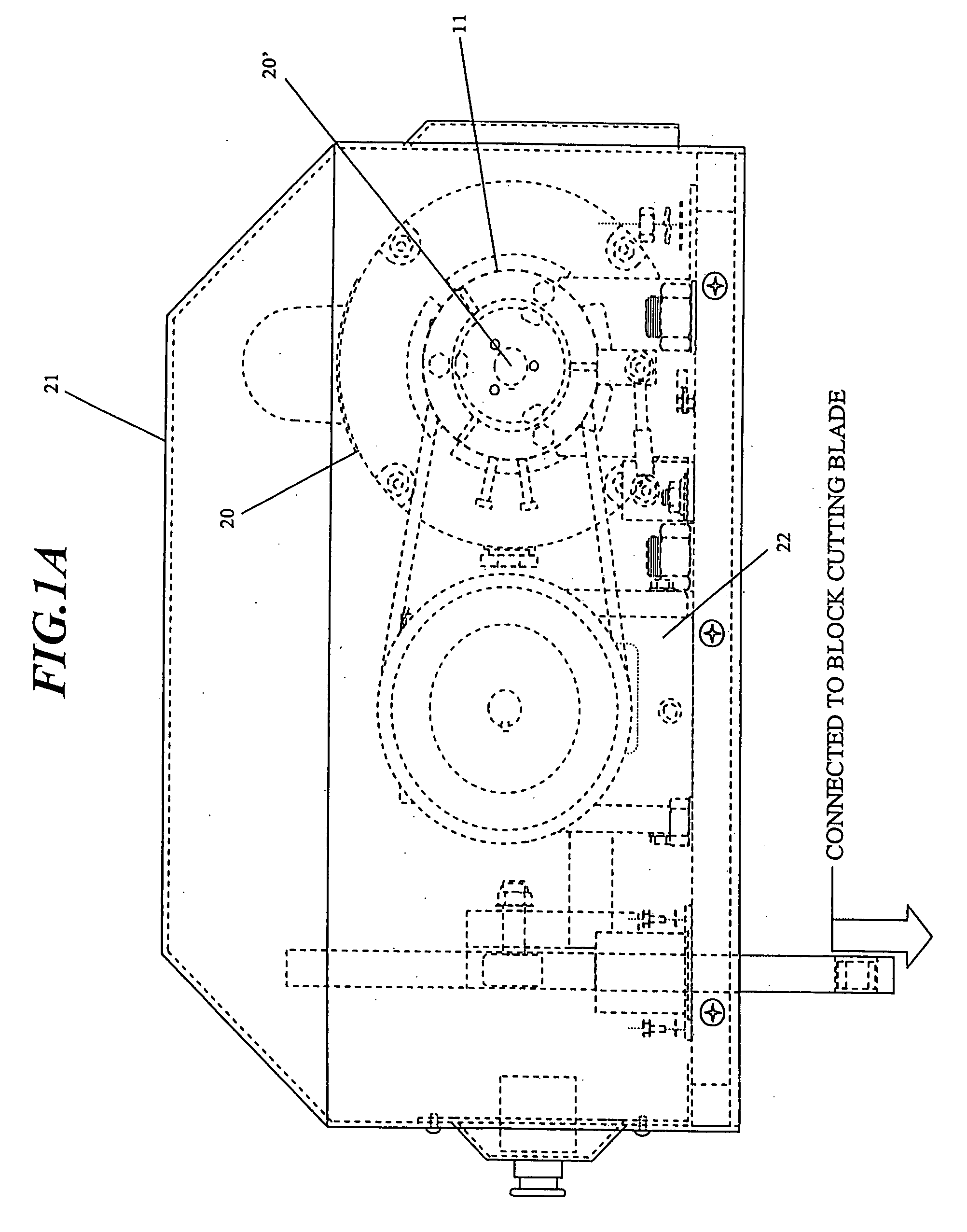
[0019]Referring now to the drawings and more particularly to FIG. 1, there is shown generally at 10 the meat tenderizing machine of the present invention. The machine is constructed of stainless steel and other sanitary materials obvious to a person skilled in the art. The machine is comprised of a support frame base 12. Two pairs of vertical support rods 13 and 13′ extend vertically from a rear portion of the base 12. A meat support board 14 is displaceably supported on the base 12. A block of cutting blades 15 of a type well known in the art is displaceably secured above the base. The block of cutting blades is of the type wherein a plurality of flat cutting blades are disposed in parallel rows and in close side-by-side relationship and have a pointed end whereby to easily penetrate the meat and cut the tendons or connective tissues in the meat. Accordingly, the meat is disposed under the block of cutting blades with the grain of the meat, that is to say the tendons and connective...


PUM


Abstract

A meat tenderizing machine and method of use is described. The machine has a support base on which a meat support board is displaceably supported. A block of cutting blades is displaceably secured above the base by a support frame. A meat retaining plate is associated with the block of cutting blades. The block of cutting blades and meat retaining plate are secured to guide rods for vertical displacement above the meat support board. A drive means imparts independent vertical displacement of the meat retaining plate and the block of cutting blades. Hand-operable handles are secured to the base below the meat support board and removably secured to the board to effect displacement of the board and operation of the drive for displacement of the meat retaining plate and block of cutting blades by both hands of an operator person safely disposed. Accordingly, the hands of the operator person are protected from the block of cutting blades. The meat support board is also reversible whereby to handle large pieces of meat.

Description

TECHNICAL FIELD[0001]The present invention relates to a meat tenderizing machine and a method of use and particularly a machine wherein the hands of an operator person are protected during operation there and further wherein large and thick pieces of meat can be handled and tenderized by the machine.BACKGROUND ART[0002]A variety of meat tenderizing machines are known and some including rolls of knives wherein pieces of meat are fed therethrough by actuating the rolls of knives. Such machines usually can handle only small pieces of meat and also cannot handle thick pieces and are dangerous to the operator's fingers. More recently, machines have been developed which comprise a block of narrow cutting blades supported above a meat support platform and which are actuated to penetrate a piece of meat positioned thereunder whereby to tenderize the meat. The meat is usually oriented with the tendons or connecting tissues in the meat transverse to the flat cutting edges of these blades wher...

Claims


Application Information

Patent Timeline
IPC IPC(8): A22C9/00
CPCA22C9/008
Inventor BOULANGER, GILLES
Owner LUMAR IDEAL II
Learn More