Manipulator system

a manipulator and manipulator technology, applied in the field of manipulators and manipulators, can solve the problem that other controllers inconveniently cannot recognize the usage history of the working unit, and achieve the effect of reducing the number of manipulators

Inactive Publication Date: 2008-10-23
TERUMO KK +1
View PDF10 Cites 1698 Cited by
  • Summary
  • Abstract
  • Description
  • Claims
  • Application Information

AI Technical Summary

Benefits of technology

[0020]It is one of the objects of the present invention to provide a manipulat

Problems solved by technology

The long incision site can be a significant concern because it is subject to infection and is often the most traumatic and painful part of the patient's recover.
However, in a case where a plurality of controllers to be connected are pr

Method used


Image

  • Manipulator system
  • Manipulator system
  • Manipulator system

Examples


Embodiment Construction

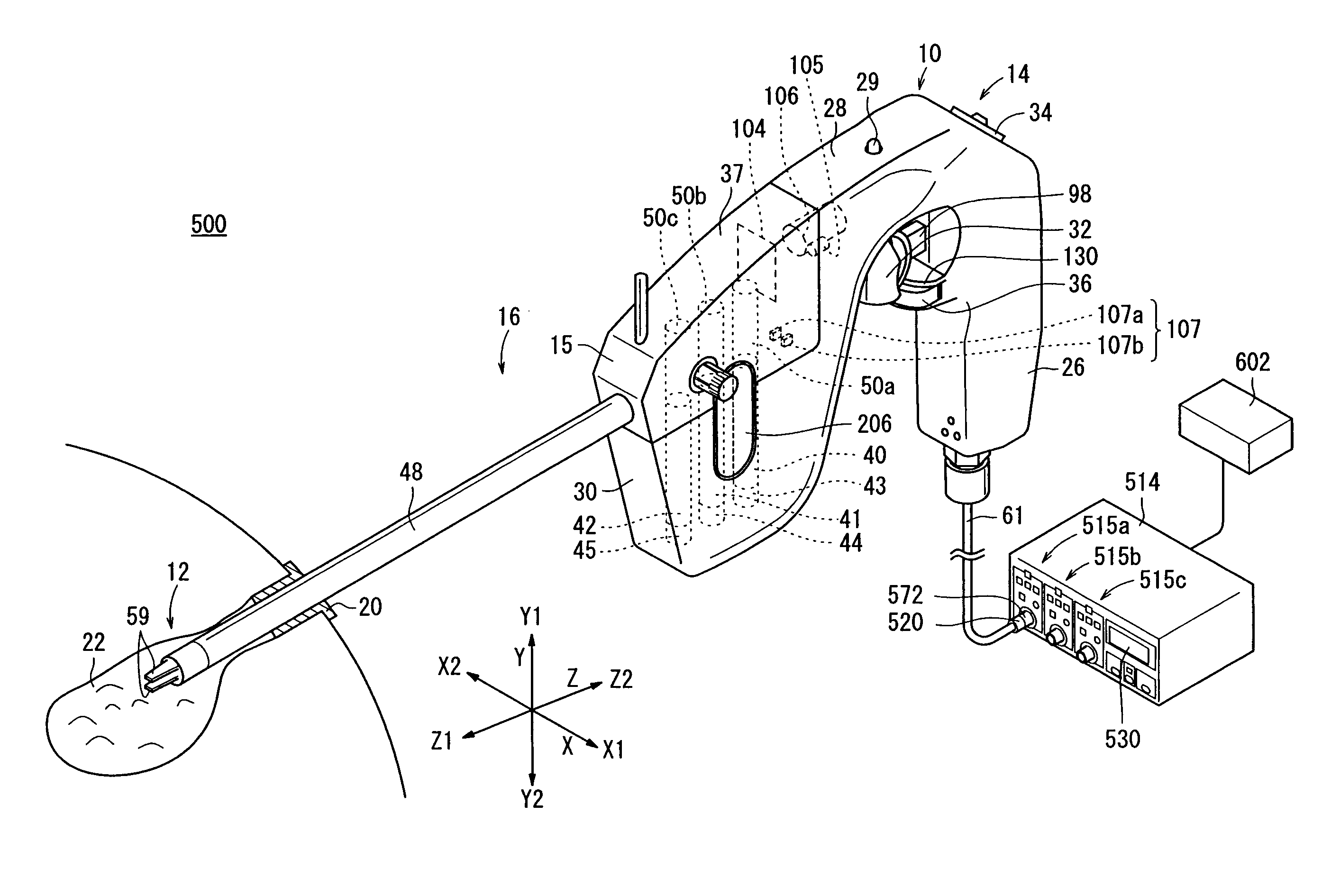
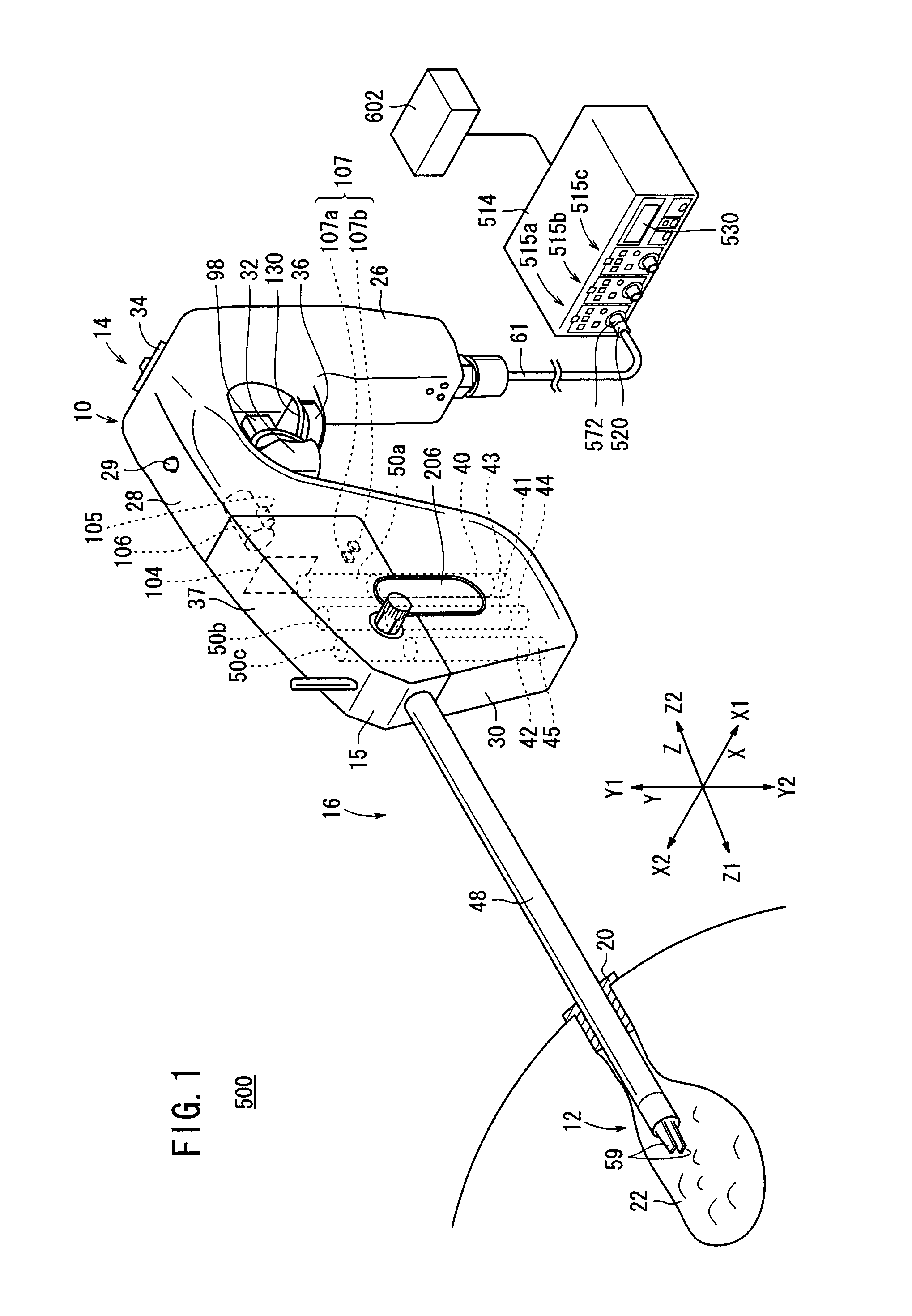
[0050]A medical manipulator system 500 according to an embodiment of the present invention will be described below with reference to FIGS. 1 to 20. The manipulator system 500 shown in FIG. 1 is used in a laparoscopic operation, etc.

[0051]As shown in FIG. 1, the manipulator system 500 has a manipulator 10 and a controller 514.

[0052]A connector 520 is disposed in a connecting portion between the manipulator 10 and the controller 514 such that the manipulator 10 is removable from the controller 514.

[0053]The manipulator 10 is intended to grasp a part of a living body, a curved needle, or the like using an end working portion 12, thereby carrying out a predetermined procedure. The manipulator 10 has a basic structure containing an operating unit 14 and a working unit 16. The controller 514 electrically controls the manipulator 10, and is connected via the connector 520 to a cable 61 extending from the lower end of a grip handle 26.

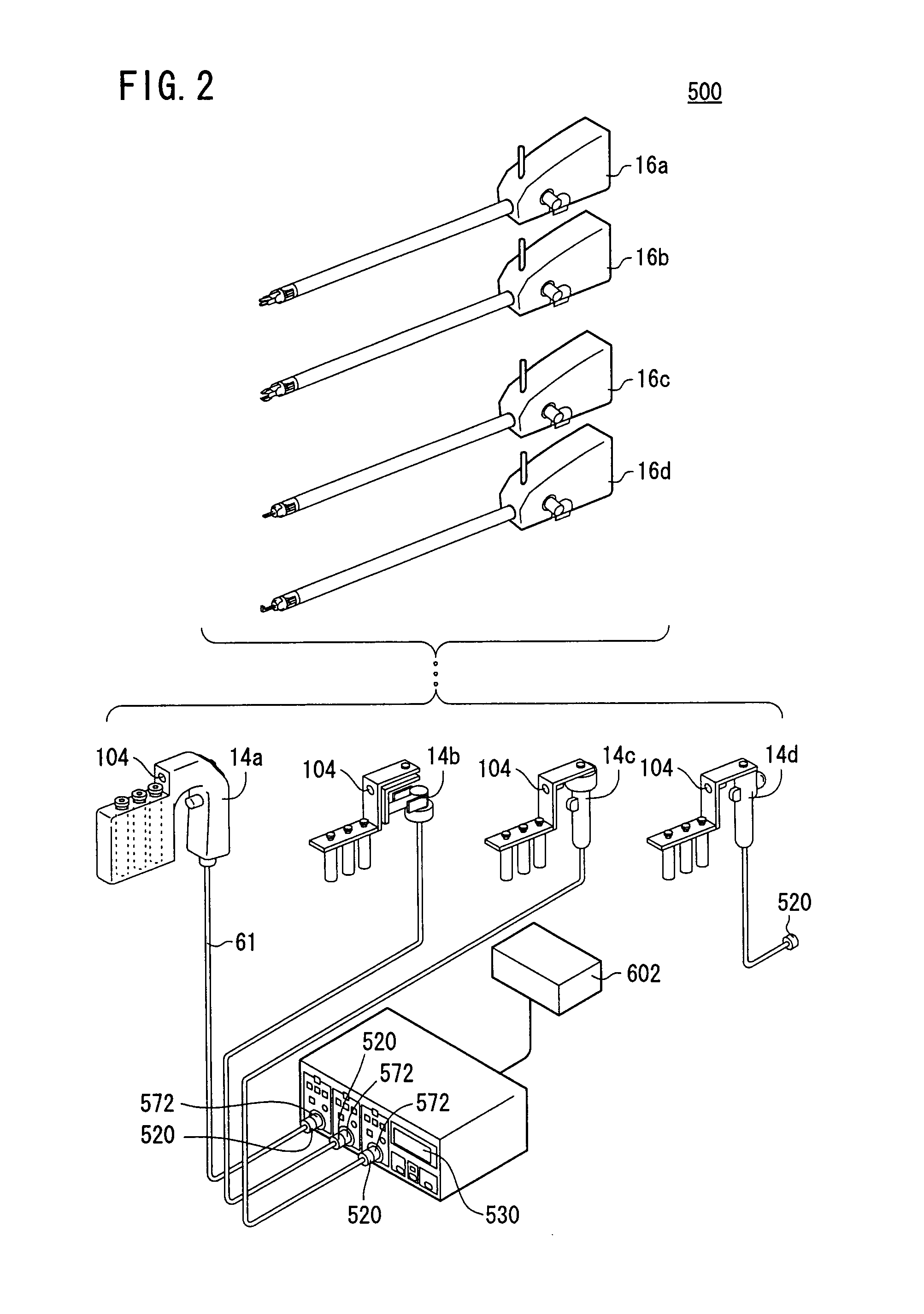
[0054]The controller 514 can simultaneously control thre...


PUM


Abstract

A manipulator comprises an actuator block and a working unit attachable to and detachable from the actuator block. The actuator block has a motor, the working unit has a connecting shaft and an end working portion disposed at the distal end thereof, and the end working portion is rotated in conjunction with the motor. The working unit further has a two-dimensional code holding an identification signal, and the actuator block further has an infrared camera for recognizing the identification signal in the code and supplying it to a controller, is the camera being not in contact with the code. The controller controls the working unit based on the supplied identification signal.

Description

BACKGROUND OF THE INVENTION[0001]1. Field of the Invention[0002]The present invention relates to a manipulator and a manipulator system for controlling the manipulator, more specifically to a manipulator system comprising a manipulator, which contains an actuator unit having an actuator and a working unit, attachable to and detachable from the actuator unit, having a working portion movable in conjunction with the actuator.[0003]2. Description of the Related Art[0004]According to laparoscopic surgery, it is customary to form a plurality of holes in the abdominal part of the patient, insert an endoscope and a manipulator (or forceps) into the respective holes, and perform the surgical operation while images captured by the endoscope are being observed on a display monitor by the surgeon. Since such a laparoscopic surgical operation does not require the abdominal cavity to be opened, the burden on the patient is small and the number of days which the patient needs to recover and spend...

Claims


Application Information

Patent Timeline
IPC IPC(8): B25J13/00
CPCA61B19/22A61B19/44A61B19/5212A61B19/5225A61B2017/00398A61B2017/0046A61B2017/00482A61B2019/2242A61B2019/2249A61B2019/442A61B2019/448A61B2019/4815A61B2019/4826A61B2019/521A61B90/96A61B2090/0805A61B34/70A61B34/71A61B2090/309A61B90/361A61B34/72A61B90/90A61B90/98A61B2090/0803A61B90/37
Inventor OMORI, SHIGERUSANO, HIROAKIHITOTSUYANAGI, MASAOJINNO, MAKOTO
Owner TERUMO KK
Why Eureka
Try Eureka