Method and system for modelling petroleum migration

a technology of petroleum migration and method, applied in the field of method and system for modeling petroleum migration, can solve the problems of crude model when compared to the real world, affecting the quality of oil and gas flow, and incorporating considerable inherent uncertainties, etc., and limiting their application and quality.

Active Publication Date: 2008-10-23
HALLIBURTON GRP CANADA
View PDF16 Cites 7 Cited by
  • Summary
  • Abstract
  • Description
  • Claims
  • Application Information

AI Technical Summary

Benefits of technology

[0005]In accordance with one embodiment, there is provided a method for modelling the migration of reactant in a subsurface petroleum system, the method comprising: generating a mesh for an area of said petroleum system, the mesh comprising a plurality of nodes, and each node representing a point in space in the area; calculating one or more variables representing one or more physical characteristics at each node in the area; determining the migration of reactant in the petroleum system based on the one or more variables.

Problems solved by technology

While this conventional approach captures many coarse features of the mesh, the grid can result in a model which is crude when compared the real world, incorporating considerable inherent elements of uncertainty.
Such crudeness often distorts or destroys details that are important in determining the correct migration of reactants within the mesh.
All of these methods have been successfully applied and their strengths have been well documented, but all are also characterized by weaknesses which have limited their application and the quality of the results.
For example, by imposing a regular grid and converting all internal inclined planes into horizontal planes in a staircase configuration, internal watersheds, natural directions of flow, are poorly approximated by such staircase structures, possibly resulting in migration pathways that are inconsistent with the underlying geometry.

Method used


Image

  • Method and system for modelling petroleum migration
  • Method and system for modelling petroleum migration
  • Method and system for modelling petroleum migration

Examples


Embodiment Construction

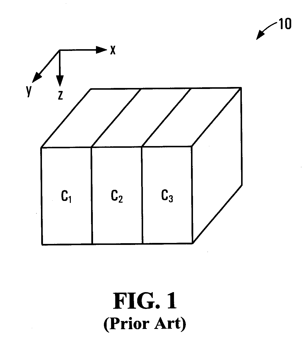
[0023]FIG. 1 is a perspective view of a three-dimensional orthogonal grid 10 used to model subsurface structures in accordance with a conventional modelling technique. The use of a three-dimensional grid such as grid 10 is well known in the art of migration modelling. Grid 10 is made up of cells C1, C2 and C3, though a typical grid used in prior art systems would be made up of hundreds if not millions of such cells. Each one of cells C1, C2 and C3 is made up of one or more cell faces, some of which are hidden from view.

[0024]To accurately predict the flow of reactants, a model is built by imposing a grid such as grid 10 on to the petroleum system to facilitate the solution of flow equations by calculating the likelihood of reactant flow between the cells. The goal is to assemble a grid which represents a three-dimensional model of the petroleum system.

[0025]Variables are calculated for each cell which can include one or more of length, width, thickness, porosity, capillary threshold...


PUM


Abstract

A method for modelling the migration of reactant in a subsurface petroleum system is described. The method comprises in part generating a mesh for an area of the petroleum system. The mesh comprises a plurality of nodes, with each node representing a point in space in the area. The method also comprises calculating one or more variables representing one or more physical characteristics at each node in the area and determining the migration of reactant in the petroleum system based on the one or more variables. The method can also handle multiple reactant phases and non-static meshes.

Description

FIELD OF THE INVENTION[0001]The present invention relates generally to the fields of basin and reservoir simulation and the modelling of subsurface oil and gas flow.BACKGROUND[0002]Basin modelling is important for oil and gas exploration and production. One of the goals of basin modelling, and often associated reservoir filling studies, is to calculate the migration of non-aqueous reactants (most commonly petroleum, which may represent one or more chemical species) in subsurface deposits of complex geometry. To accomplish this goal, the system under study will usually be described by a grid system, with each cell of the grid being assigned petrophysical properties that describe how they will affect fluid flow. Where a three-dimensional model of a basin or reservoir, consisting of porous or fractured media, (hereafter collectively referred to as a “petroleum system”) is being developed, a mesh of elements is imposed over the space under study. The mesh is usually (but not exclusively...

Claims


Application Information

Patent Timeline
Patent Type & Authority Applications(United States)
IPC IPC(8): G06G7/57
CPCE21B49/00G01V1/30
Inventor CARRUTHERS, DANNEUFELD, CHRISTOPHER
Owner HALLIBURTON GRP CANADA
Why Eureka
Try Eureka