Apparatus and method for supporting model-driven development

a model and development method technology, applied in the direction of software maintenance/management, program control, instruments, etc., can solve the problems of reducing development costs, shortening the development period, and the model defined in the upper layer needs to be considered as one to be changed inevitably

Active Publication Date: 2008-10-23
IBM CORP
View PDF27 Cites 35 Cited by
  • Summary
  • Abstract
  • Description
  • Claims
  • Application Information

AI Technical Summary

Benefits of technology

[0024]In addition, the present invention provides a program allowing a computer to function as an apparatus for supporting model-driven development. The program allows the computer to function as a first obtaining unit, a second obtaining unit and a merge unit. The first obtaining unit obtains first change information on a first change from among changes in a target model generated based on a source model in the model-driven developm

Problems solved by technology

In application development in recent years, challenges for many developers are to shorten a development period and to reduce development costs.
However, when the model-driven development is actually carried out, a model defined in an upper layer needs to be considered as one to be changed inevitably.
In this case, the problem is how to merge the impacts from the upper model and the editing in the lower model.
However, a method has not yet been developed for managing many changes in response to repeated change requests when the model-driven development is applied to a

Method used


Image

  • Apparatus and method for supporting model-driven development
  • Apparatus and method for supporting model-driven development
  • Apparatus and method for supporting model-driven development

Examples


Embodiment Construction

[0040]Hereinafter, the best modes (hereinafter, called embodiments) for carrying out the invention will be described in detail by referring to the accompanying drawings.

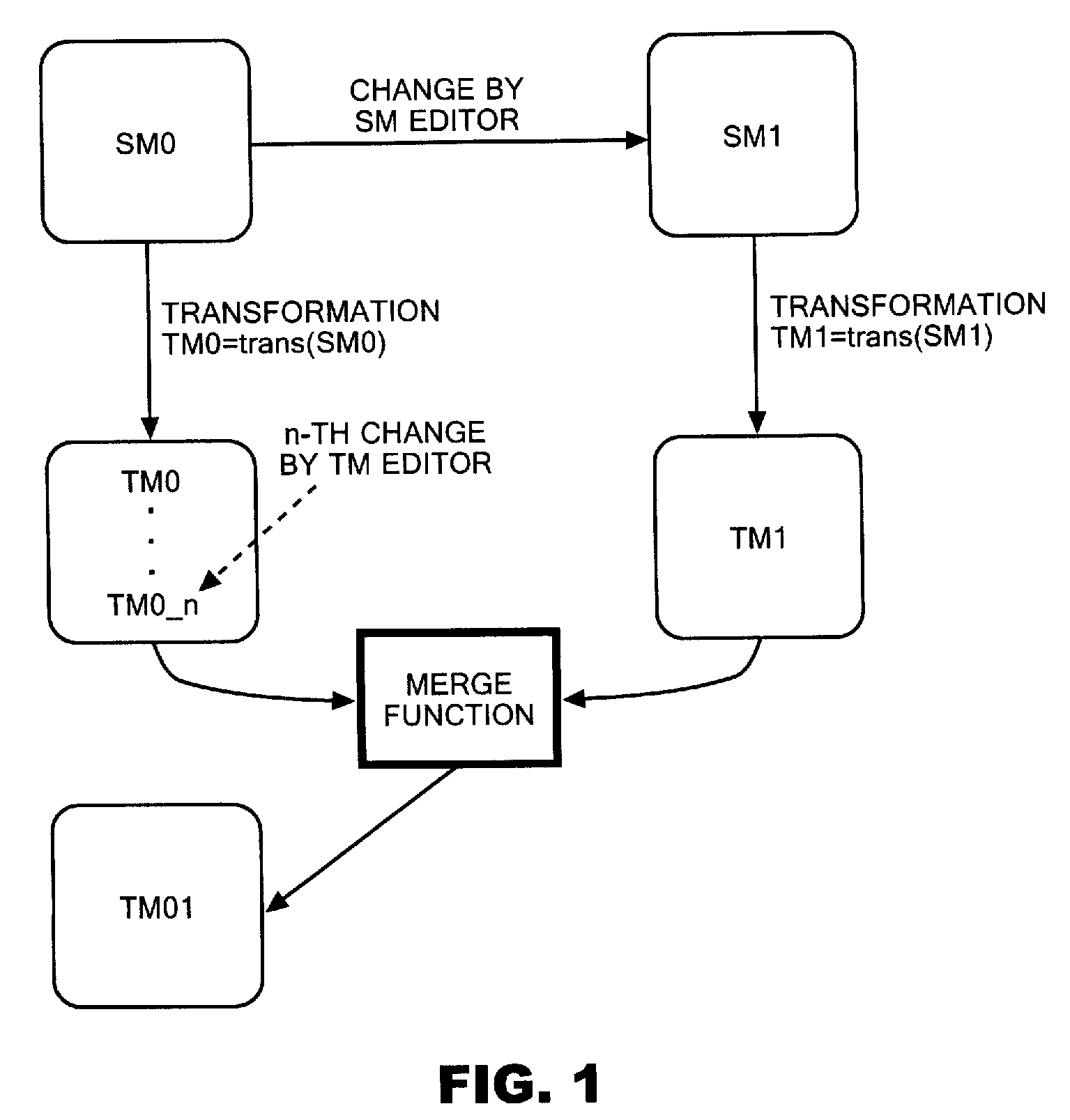
[0041]FIG. 1 is a diagram showing a source model that is an input for a model transformation, a target model that is an output of the model transformation, and processes of changing each model and merging the models. The source model and the target model resulting from the first model transformation are denoted by SM0 and TM0, respectively. In addition, SM1 denotes the source model obtained when a person in charge of editing the source model (called an SM editor, below) changes SM0, and TM1 denotes the target model obtained through the model transformation of SM1. Moreover, TM0_n denotes the target model obtained through the n-th change of TM0 by a person in charge of editing the target model (called a TM editor, below).

[0042]Here, When TM01 that is the latest target model is generated from TM1 and TM0_n, it is neces...


PUM


Abstract

In a model editing apparatus, a model transformation function transforms SM (source model) 0 into TM (target model) 0, and generates TDM (transformation dependency model) 0. Moreover, when an SM editor generates SM1 by updating SM0, the model transformation function transforms SM1 into TM1 and generates TDM1. When a TM editor generates TM0_n by editing TM0 independently of the change in SM0, a Change element registration function registers a difference Δ2 between TM0 and TM0_n in TDM0, thereby generating TDM0_n. Then, in response to a call, a merge function merges a difference Δ1 between TDM0 and TDM1 extracted by a Δ1 extraction function, and a difference Δ2 extracted from TDM0_n, according to prestored processing patterns.

Description

CROSS-REFERENCE TO RELATED APPLICATIONS[0001]This application claims priority under 35 U.S.C. § 119 to Japan Patent Application No. 2007-109181 filed Apr. 18, 2007, the entire content of which is specifically incorporated by reference herein.BACKGROUND OF THE INVENTION[0002]1. Field of the Invention[0003]The present invention relates to an apparatus and method for supporting model-driven development. In particular, the present invention relates to an apparatus and method for merging changes in a model in model-driven development.[0004]2. Description of Related Art[0005]In a collaborative development environment where multiple developers are engaged in development of the same application, since the developers individually change the application, it is important to merge differences in the application resulting from the individual changes in the application. Heretofore, such merging is carried out by use of a function in a tool, such as Concurrent Versions System (CVS) and Rational (r...

Claims


Application Information

Patent Timeline
IPC IPC(8): G06F9/44
CPCG06F8/35G06F8/71G06F8/355G06F8/20G06F8/10
Inventor NEROME, TAKASHISAWATANI, YURIKOSUZUMURA, TOYOTAROFUJIWARA, KAORI
Owner IBM CORP
Why Eureka
Try Eureka