Overlay Speed Improvements for a layout control system

Active Publication Date: 2018-11-15
IRELAND ANTHONY JOHN
View PDF0 Cites 1 Cited by
  • Summary
  • Abstract
  • Description
  • Claims
  • Application Information

AI Technical Summary

Benefits of technology

[0014]Improvement of the operating speed and hence number of simultaneously supportable devices and reduction of perceived task latency of an existing and/or new installation layout control system ar

Problems solved by technology

DCC ‘0’ bits are costly in terms of lost d

Method used


Image

  • Overlay Speed Improvements for a layout control system
  • Overlay Speed Improvements for a layout control system
  • Overlay Speed Improvements for a layout control system

Examples


Embodiment Construction

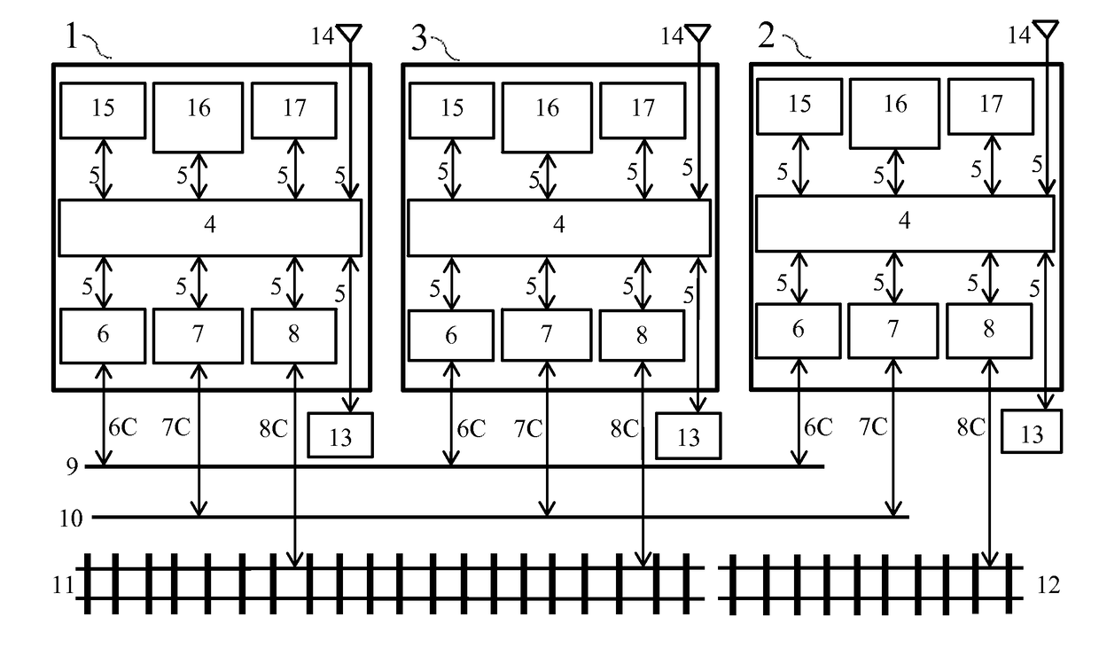
[0036]Primary control unit 1 of FIG. 1 item 1 (herein also ‘Command Station’) represents a system control device means configured to be interconnected in a system that may include unidirectional and bidirectional data link means; track connection 8C to primary layout tracks 11 as a predominant data sink, and / or other connections or links to information / data sources. Primary control unit 1 is broadly comprised of; an implemented control unit logic 4 that animates, sequences and configures 1 to perform any pre-defined primary control task(s) required, based on setup data obtained from configuration storage 15 means, and instances of internal data exchange path 5 means connecting to other logical component means, such as; data network interface 6, power interface 8, auxiliary control interface 7, protocol codecs 16 and extra data connection 14. The functionality of each of these component means is performed by associated and combined hardware and / or software elements. All the control s...


PUM


Abstract

Methods and related apparatus embodiments are disclosed that allow combinations of legacy devices and new higher capability devices to be compatibly integrated on a model railroad control system to provide; higher system speed, new control capabilities and lowered control latency delays.

Description

TECHNICAL FIELD[0001]This invention is in the field of general integrated control systems and in particular for control upgrades on model railroad layout control systems.BACKGROUND ART[0002]Control systems typically gather and / or exchange data from information sources, process this source data using an internal algorithm or control logic method, and then convey and / or exchange the processed result to information sinks, to execute an action. As a control system implementation grows, sometimes organically, it will often require more resources, and in particular may require upgraded capability, to both; process a greater data exchange volume and / or do this at a higher net data throughput rate. This is true for digital scale model railroad layout control systems, as new and lower cost technologies become available that allow users to; assert faster and / or better control and operation of associated system devices, allow for new types of control features and layout operation automation, a...

Claims


Application Information

Patent Timeline
IPC IPC(8): A63H19/24
CPCA63H19/24A63H2019/246
Inventor IRELAND, ANTHONY JOHN
Owner IRELAND ANTHONY JOHN
Why Eureka
Try Eureka