Combination wheel chock and ballast weight for motor vehicles

a technology of motor vehicles and ballast weights, applied in the field of wheel chocks, can solve the problems of wheel chocks, easy to move cars or trucks, and inability to move, and achieve the effect of increasing traction

a technology of motor vehicles and ballast weights, applied in the field of wheel chocks, can solve the problems of wheel chocks, easy to move cars or trucks, and inability to move, and achieve the effect of increasing traction

US20080264734A1Inactive Publication Date: 2008-10-30WALTER EDWARD J

Image

  • Combination wheel chock and ballast weight for motor vehicles
  • Combination wheel chock and ballast weight for motor vehicles
  • Combination wheel chock and ballast weight for motor vehicles

Examples


Embodiment Construction

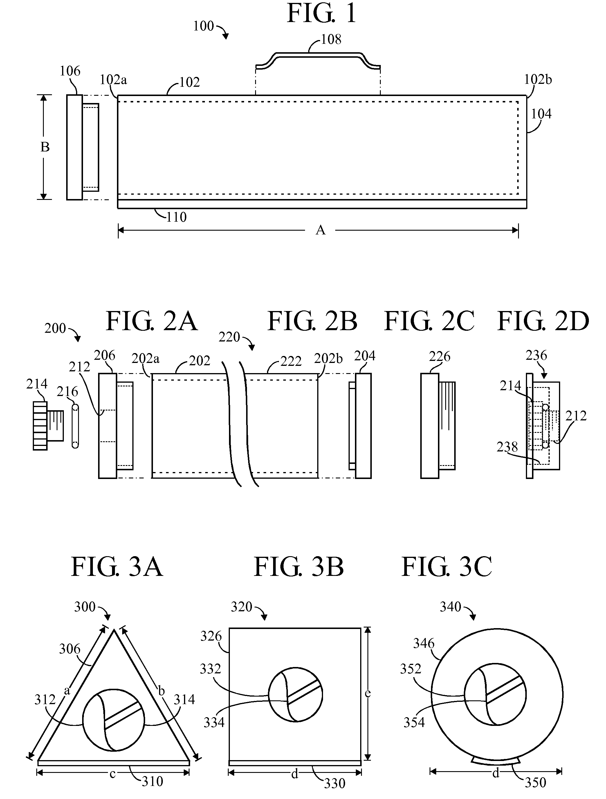
[0061]FIG. 1 illustrates an embodiment of a combination wheel chock and ballast weight 100 for motor vehicles. The apparatus 100 is essentially a container comprising elongate tubular body 102, having two opposite ends—a front end 102a and a back end 102b, a length “A”, and a height “B”. (Please note that FIG. 1 is a schematic illustration, and nothing limiting about the cross section of the body should be implied, inferred, or concluded from this drawing.) The body 102 is hollow, so that it can be filled with a flowable material (not shown) such as a liquid (such as water), or a particulate solid (such as sand or salt particles). The body may 102 may be formed of metal, or of plastic.

[0062]The back end 102b of the container 100 is shown as being closed, as indicated by the wall 104. The front end 102a of the container 100 is shown as being open.

[0063]A separate closure member (end cap) 106 is adapted to close the front end 102a of the container 100 so that flowable material may be ...


PUM


Abstract

A container fillable with a flowable material such as sand, salt or water, and usable as a ballast weight for a back of a motor vehicle and also as a wheel chock. The container is elongate and may have a triangular cross section. One end may be permanently closed. An end cap at the other end may be removed for filling / emptying the container, or may have a hole sealed by a plug or a cap for filing / emptying the container. An anti-skid surface element may provided on an external surface of the body. A separate handle may be provided, or an integral handle may be provided. Stripes of a color contrasting with the body member may be disposed on at least two sides of the body member. The container may be formed of a rigid metal or plastic.

Description

TECHNICAL FIELD OF THE INVENTION[0001]In one aspect, the present invention relates generally to wheel chocks. In another aspect, the invention relates to ballast containers to add weight for improved traction in motor vehicles.BACKGROUND OF THE INVENTION[0002]Wheel chocks are used to prevent the wheels of a vehicle, such as an automotive vehicle or airplane, from moving. For example, a car or truck parked on a hill might move if the emergency brake is defective. Or, it is often good practice to immobilize the wheels of an automotive vehicle when working on it, particularly if jacking it up might defeat the immobilizing function of a parking brake. In the case of airplanes, chocks are often used to prevent a parked airplane from being moved by wind forces.[0003]Adding ballast weight to an automotive vehicle to increase traction, particularly for winter driving, is well known.[0004]U.S. Pat. No. 5,330,227 (“227 patent”) discloses storable truck bed weights for improved traction and ha...

Claims


Application Information

Patent Timeline
30 Oct 2008
Publication
US20080264734A1
IPC
B60T3/00
CPC
B60T3/00
Inventors
WALTER, EDWARD J.