Method and System for Controlling RFID Transponder Response Waiting Periods

Active Publication Date: 2008-10-30
ZEBRA TECH CORP
View PDF12 Cites 23 Cited by
  • Summary
  • Abstract
  • Description
  • Claims
  • Application Information

AI Technical Summary

Benefits of technology

[0011]One object of the present invention is striving to provide simpler methods of adjusting the Round Size so as to de

Problems solved by technology

However in the situation where many tags may be present in a reader's field of views, such as a crowd of people, or a pallet load of goods having tags attached, the transmissions by the tags would occur together and cause collisions, rendering the transmissions unusable due to mutual

Method used


Image

  • Method and System for Controlling RFID Transponder Response Waiting Periods
  • Method and System for Controlling RFID Transponder Response Waiting Periods
  • Method and System for Controlling RFID Transponder Response Waiting Periods

Examples


Embodiment Construction

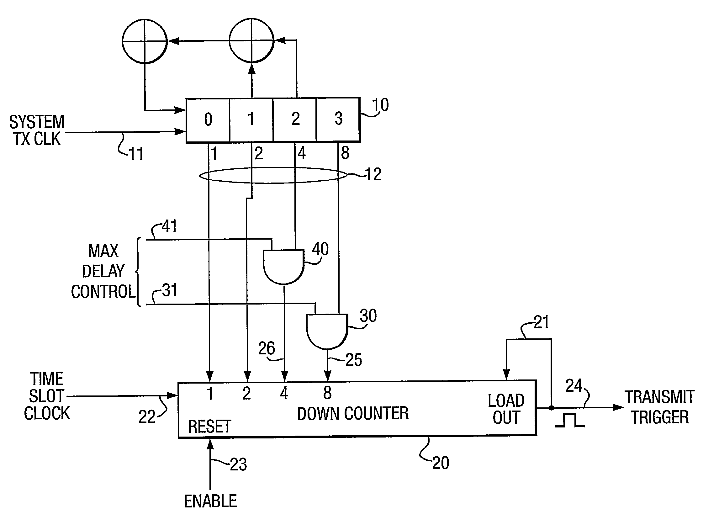
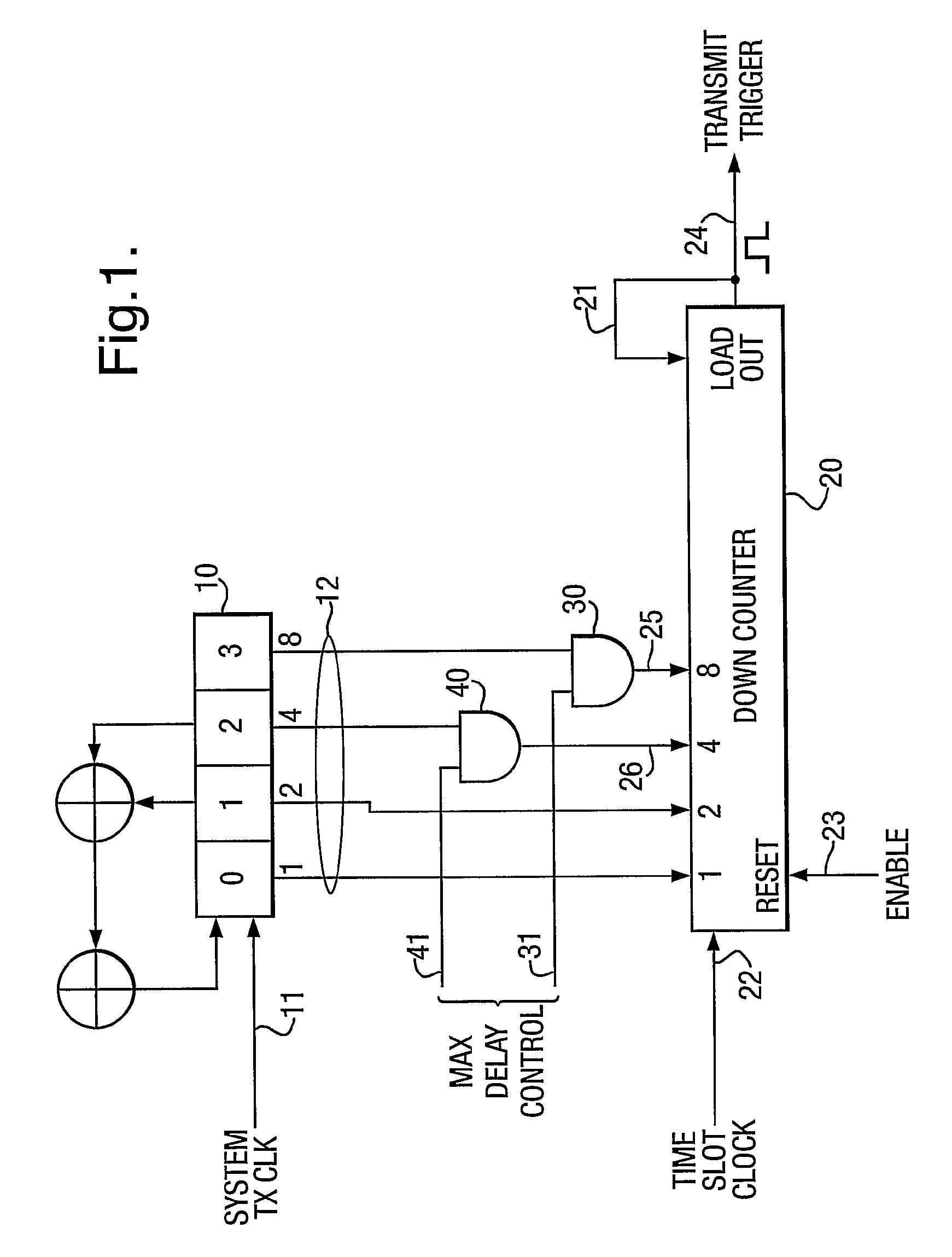
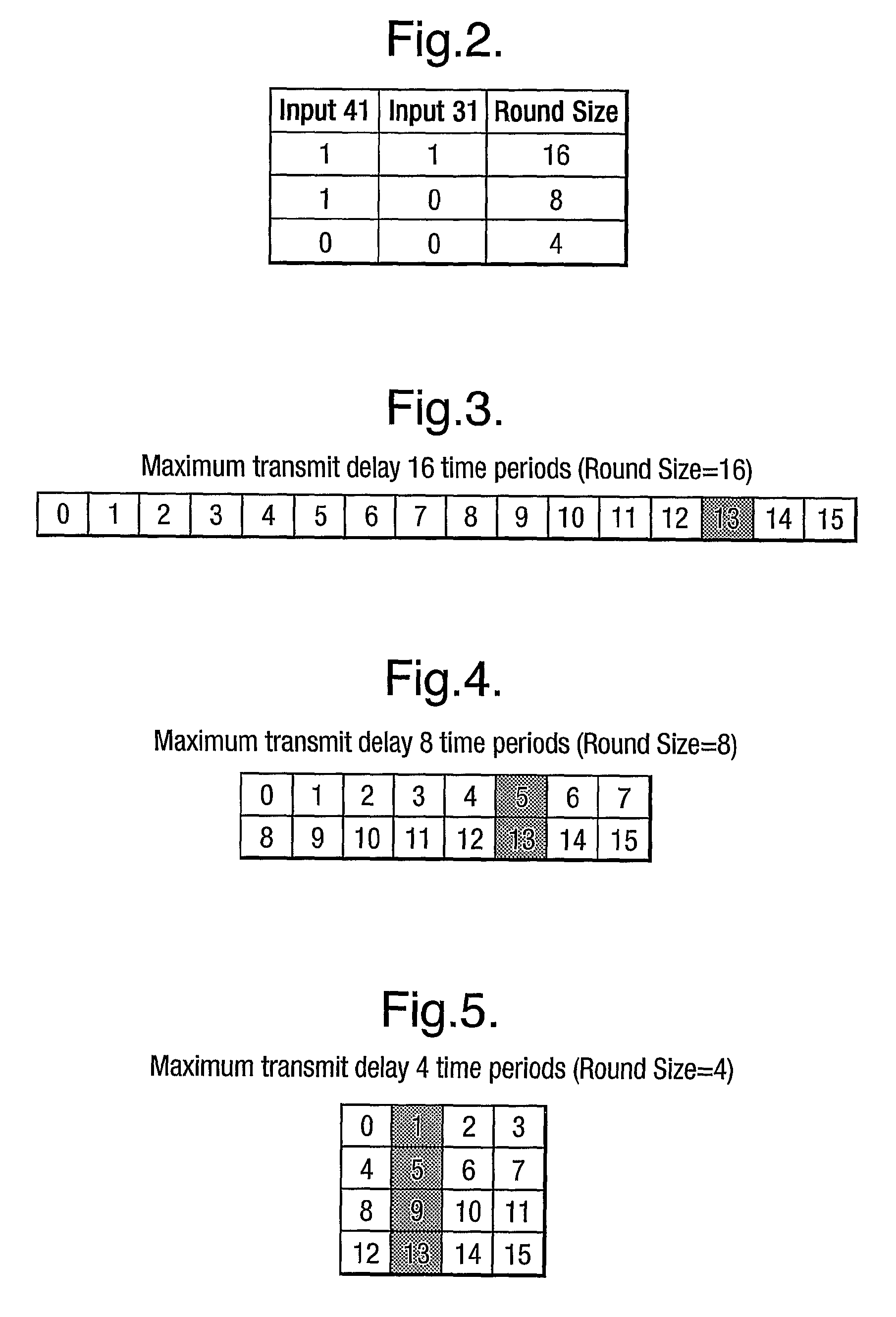
[0034]For the purposes of this description a simplified logic circuit FIG. 1 will be used to illustrate the principle. This simplified logic circuit comprises a 4 bit pseudo-random number generator (PRNG) 10, a 4 bit down counter 20 and two AND gates 30 and 40. The PRNG is driven by the system clock on input 11. The PRNG continuously generates a random number which is presented to the outputs 12, on binary lines representing weighted binary values 1, 2, 4 and 8. Binary lines 1 and 2 are routed directly to the 1 and 2 preload inputs of down counter 20. Binary lines 4 and 8 are routed first to one input of each of AND gates 40 and 30 respectively. The second input of each AND gate 41 and 31 respectively, are used to control the Round Size as shown in FIG. 2. The outputs of each of these AND gates is routed to the binary 4 and binary 8 inputs, 26 and 25 of the 4 bit down counter 20. Refer now to FIG. 3. The diagram illustrates a round having a size of 16 time intervals or slots labelle...


PUM


Abstract

The invention describes an arbitration management method and system for use in identifying RFID transponders or tags which each transmit a response signal to a reader within a respective waiting period the maximum duration of which can be adjusted. The maximum duration is determined by a random number transmitted to a counter along a number of data lines, at least one of the data lines being provided with logic gates which block or permit data line signals reaching the binary inputs of the counter to control the maximum length of the waiting period.

Description

FIELD OF INVENTION[0001]This invention relates to an arbitration management method for use in identification systems, more particularly, but not exclusively, in RFID systems. There is provided a method of identifying a plurality of transponders each of which transmits data at intervals to a receiver. The invention also relates to an identification system comprising a plurality of transponders and a receiver, to the transponders themselves and to an integrated circuit for use in a transponder.BACKGROUND TO THE INVENTION[0002]Identification systems are known in which a plurality of transmitters, typically transponders (commonly called tags), are activated by a power signal (or an “interrogation signal”) and then transmit signals, usually containing identification data to a receiver, which typically forms part of the interrogator. The signals may be transmitted in many ways, including electromagnetic energy, eg. radio frequency (RF), infra red (IR), coherent light and sound, eg. ultra-...

Claims


Application Information

Patent Timeline
IPC IPC(8): H04Q5/22G06K7/00G06K19/07
CPCG06K7/10059G06K19/0723G06K7/0008
Inventor TURNER, CHRISTOPHER GORDON GERVASEMCMURRAY, JOHN
Owner ZEBRA TECH CORP
Why Eureka
Try Eureka