
Predictive autofocusing

a technology of pre-determined autofocusing and imaging device, applied in the field of imaging, can solve the problems of reducing the optimization brought by a skilled human operator, difficult to maintain the sample at the optimal focal position, and single reference point may lack sufficient information for accurate autofocusing

Active Publication Date: 2008-10-30
LEICA MICROSYSTEMS CMS GMBH
View PDF13 Cites 56 Cited by
  • Summary
  • Abstract
  • Description
  • Claims
  • Application Information

AI Technical Summary

Benefits of technology

[0006]Therefore, there is a need for an imaging device that performs accurate rapid autofocusing in real-time image acquisition applications.

Problems solved by technology

However, fully automated microscopy eliminates the optimization brought by a skilled human operator, such as the task of keeping the sample in focus during observation.
Accordingly, it is difficult to maintain the sample at the optimal focal position due to variations in the sample.
Although this approach may provide rapid autofocusing, the single reference point may lack sufficient information for accurate autofocusing.
Although this approach may provide more accurate autofocusing than the use of a laser beam, acquisition of the numerous images often creates time delays that prevent rapid autofocusing.

Method used


Image

  • Predictive autofocusing
  • Predictive autofocusing
  • Predictive autofocusing

Examples


Embodiment Construction

[0020]In the following detailed description, numerous specific details are set forth in order to provide a thorough understanding of various embodiments of the present invention. However, those skilled in the art will understand that embodiments of the present invention may be practiced without these specific details, that the present invention is not limited to the depicted embodiments, and that the present invention may be practiced in a variety of alternative embodiments. In other instances, well known methods, procedures, and components have not been described in detail.

[0021]Furthermore, various operations may be described as multiple discrete steps performed in a manner that is helpful for understanding embodiments of the present invention. However, the order of description should not be construed as to imply that these operations need be performed in the order they are presented, nor that they are even order dependent. Moreover, repeated usage of the phrase “in one embodiment...


PUM


Abstract

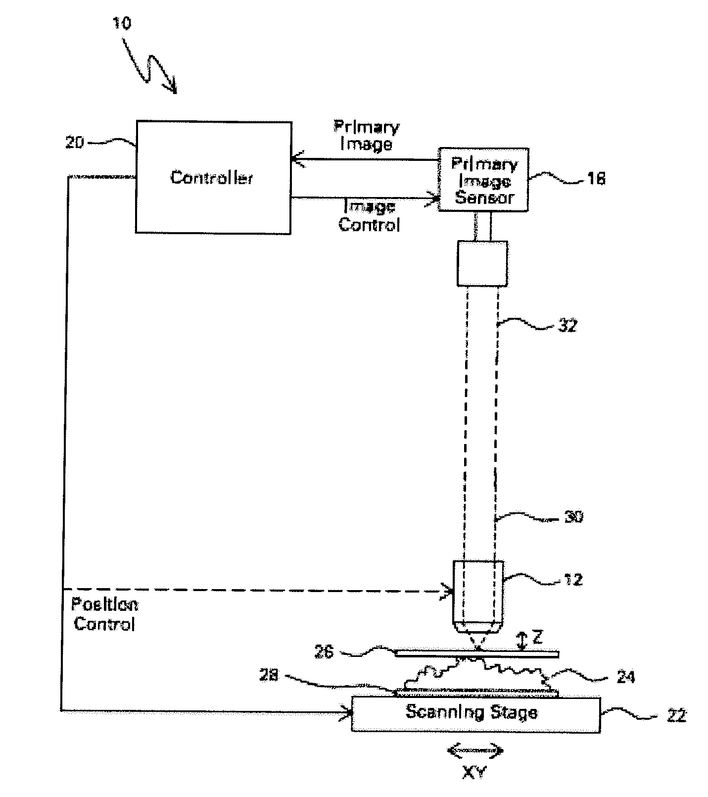
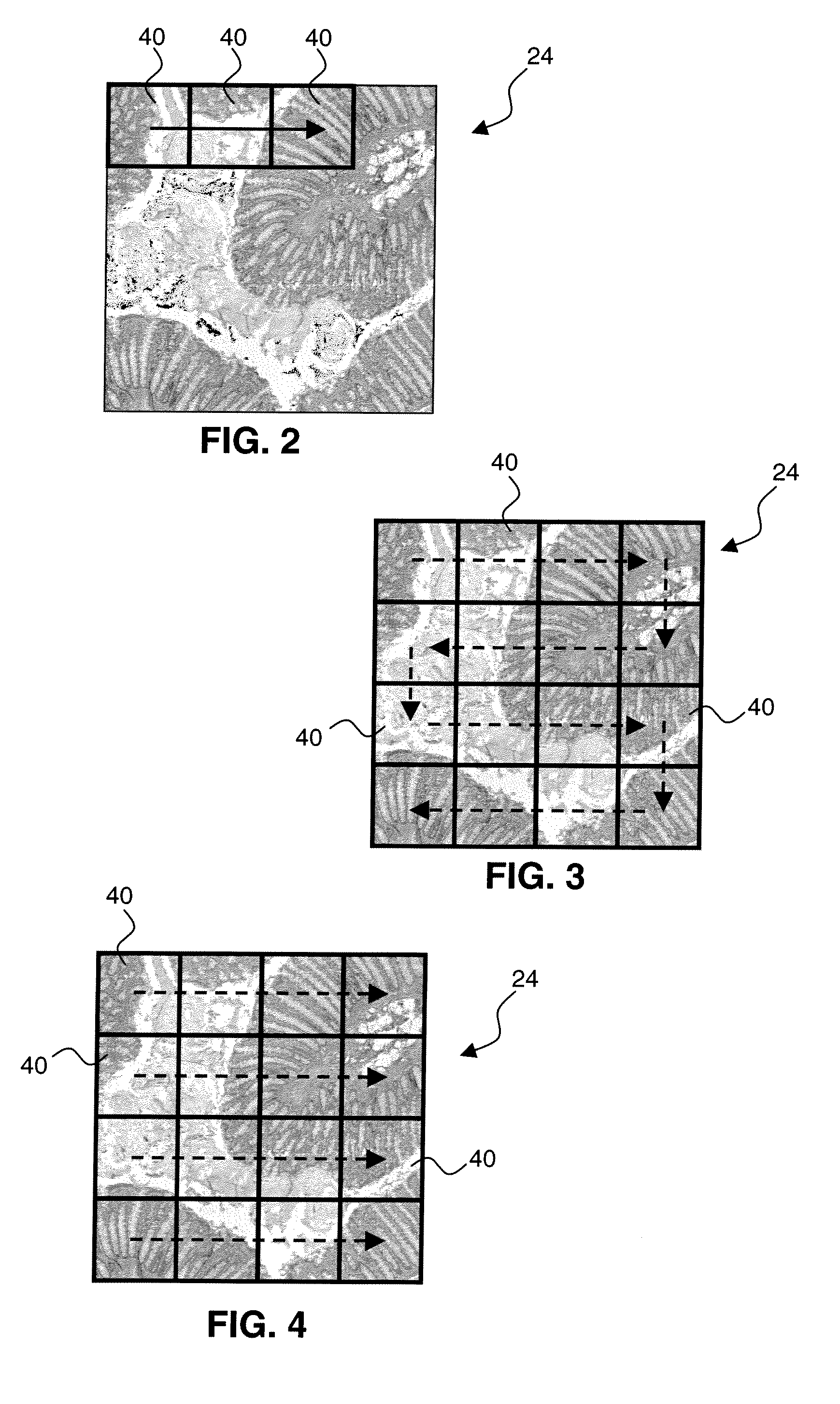
A method of autofocusing includes capturing first, second and third images of a sample, at respective first, second and third sample distances and respective first, second and third lateral positions determined with respect to an objective; determining a quantitative characteristic for the first, second and third images; determining a primary sample distance based upon at least the quantitative characteristics for the first, second, and third images; and capturing a primary image of the sample at the primary sample distance and at a primary lateral position that is offset from the first, second and third lateral positions.

Description

CROSS REFERENCE TO RELATED APPLICATIONS[0001]This application is a continuation-in-part of U.S. patent application Ser. No. 11 / 741,839 entitled “MICROSCOPE WITH DUAL IMAGE SENSORS FOR RAPID AUTOFOCUSING”, filed Apr. 30, 2007, which is herein incorporated by reference to the extent the disclosure of which does not conflict with the present application.BACKGROUND[0002]Embodiments of the present invention relate to imaging, and more particularly to predictive autofocusing of an imaging device.[0003]High-density solid-state detector technology, coupled with affordable, terabyte and higher scale data storage, has greatly facilitated digital recording of industrial and medical images. In the biological and medical realm, digital microscopy has been used for such applications as high throughput screening, archiving, telemedicine, and rapid information retrieval. Digital microscopy is often advantageous over conventional light microscopy since hands-free operation of the microscope can incr...

Claims


Application Information

Patent Timeline
Patent Type & Authority Applications(United States)
IPC IPC(8): H04N5/225H04N5/232
CPCG02B21/244G02B21/365
Inventor YAZDANFAR, SIAVASHFILKINS, ROBERT JOHNDIXON, ELIZABETH LOKENBERGDIXON, WALTER VINCENTTASIMI, KRENARKENNY, KEVIN BERNARD
Owner LEICA MICROSYSTEMS CMS GMBH
Learn More