Testing method and apparatus of thin-film magnetic head

Active Publication Date: 2008-10-30
TDK CORPARATION
View PDF4 Cites 4 Cited by
  • Summary
  • Abstract
  • Description
  • Claims
  • Application Information

AI Technical Summary

Benefits of technology

[0009]It is therefore an object of the present invention to provide testing method and apparatus of a thin-film magnetic head, whereby it is possi

Problems solved by technology

Among the thin-film magnetic heads with such GMR or TMR read head elements having a multi-layered structure, some heads may produce noises when their environment temperature becomes high.
Contrary to this, since the noise increases when the temperature increases, the thin-film magnetic head corresponding to FIG. 1b is a defective

Method used


Image

  • Testing method and apparatus of thin-film magnetic head
  • Testing method and apparatus of thin-film magnetic head
  • Testing method and apparatus of thin-film magnetic head

Examples


Embodiment Construction

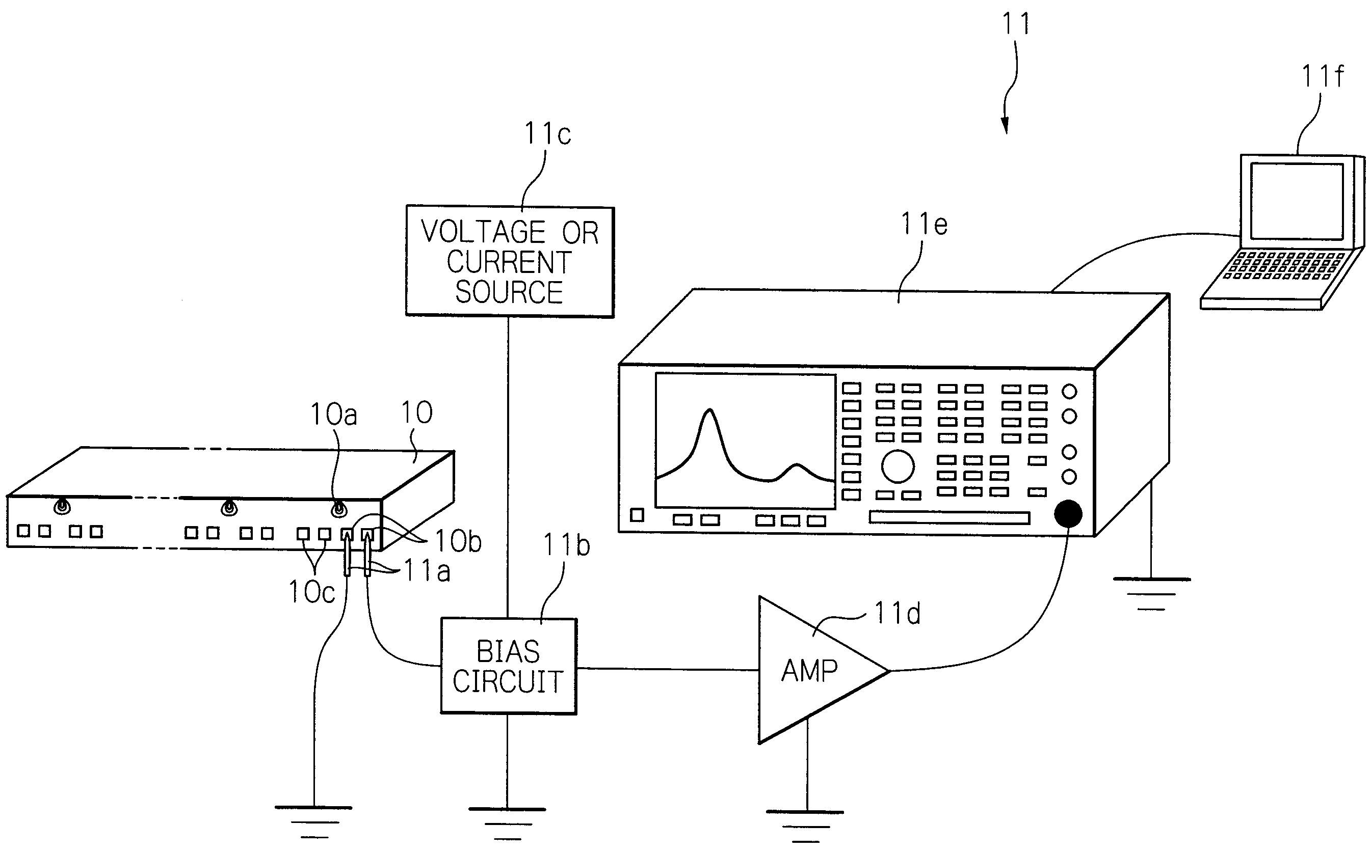
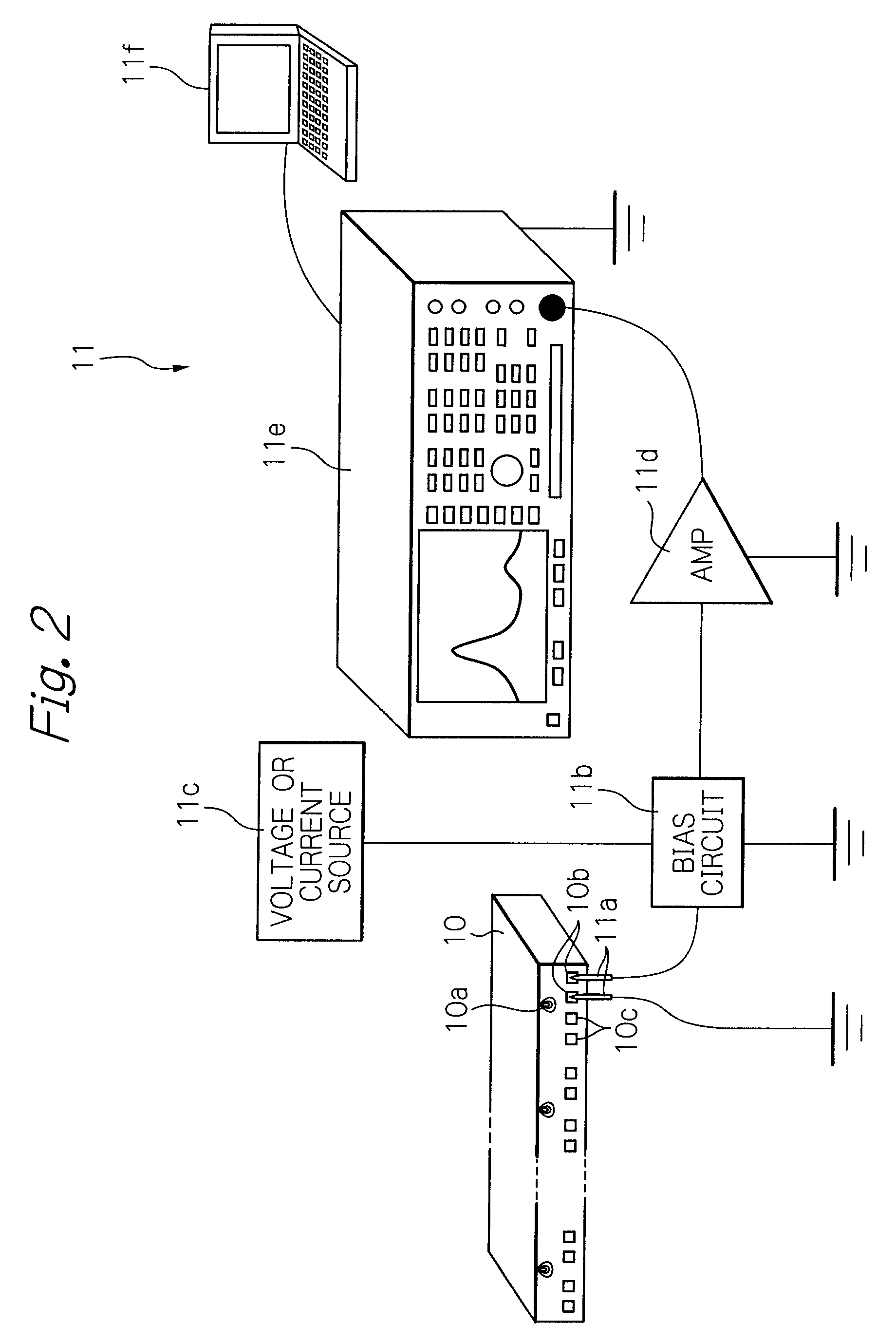
[0041]FIG. 2 schematically illustrates a configuration of a testing apparatus of a thin-film magnetic head as a preferred embodiment according to the present invention.

[0042]In the figure, reference numeral 10 denotes a bar member with a plurality of thin-film magnetic heads 10a connected in series and aligned with each other, each head having a TMR read head element, and 11 denotes the testing apparatus.

[0043]The bar member 10 is fabricated as follows. First, in the wafer process, many of thin-film magnetic heads are formed to arrange in matrix on an integration surface of a thin-film magnetic head wafer. The wafer is then cut into a plurality of bar members, and thereafter an air-bearing surface (ABS) of each bar member 10 is lapped to adjust an MR height. Each thin-film magnetic head 10a in the bar member 10 has a TMR read head element, an inductive write head element, a pair of terminal pads 10b electrically connected to the TMR read head element, and a pair of terminal pads 10c...


PUM


Abstract

A testing method of a thin-film magnetic head has an MR read head element with a multi-layered structure including a magnetization-fixed layer, a magnetization-free layer and a nonmagnetic intermediate layer or a tunnel barrier layer sandwiched between the magnetization-fixed layer and the magnetization-free layer. The method includes a step of feeding through the MR read head element a sense current, a step of measuring non-signal output versus frequency characteristics of the MR read head element over a frequency range that covers at least FMR of the magnetization-fixed layer, and a step of discriminating whether the thin-film magnetic head is a head providing high-temperature noises by comparing a frequency of a peak of the non-signal output resulting from FMR of the magnetization-fixed layer with a threshold.

Description

BACKGROUND OF THE INVENTION[0001]1. Field of the Invention[0002]The present invention relates to testing method and apparatus of a thin-film magnetic head with a magnetoresistive effect (MR) read head element having a multi-layered structure that includes a magnetization-fixed layer and a magnetization-free layer.[0003]2. Description of the Related Art[0004]As hard disk drive apparatuses (HDD) increase in capacity and reduce in size, highly sensitive and high-output thin-film magnetic heads are being demanded. In order to satisfy the demand, performance of giant magnetoresistive effect (GMR) thin-film magnetic heads with GMR read head elements are being improved. On the other hand, tunnel magnetoresistive effect (TMR) thin-film magnetic heads with TMR read head elements having a magnetoresistivity ratio more than twice as high as that of the GMR thin-film magnetic heads are being developed.[0005]Among the thin-film magnetic heads with such GMR or TMR read head elements having a mult...

Claims


Application Information

Patent Timeline
IPC IPC(8): G11B5/33G11B5/127G01R33/12
CPCB82Y10/00B82Y25/00G01R33/093G01R33/1207G11B5/3906G11B5/3909G11B5/455
Inventor SARUKI, SHUNJIUESUGI, TAKUMIUMEHARA, TSUYOSHIANTOKU, YOSUKE
Owner TDK CORPARATION
Why Eureka
Try Eureka