Shutter device and image pickup apparatus

Active Publication Date: 2008-10-30
CANON KK
View PDF2 Cites 12 Cited by
  • Summary
  • Abstract
  • Description
  • Claims
  • Application Information

AI Technical Summary

Benefits of technology

[0010]Accordingly, the present invention is directed to a shutter device which can restrict bounding of a shutter blade using a shock-absorbing member when movement of the shutt

Problems solved by technology

When the collision between the shutter blade and the rubber is repeated, scraping of the rubber is eventually started by the collision of the shutter blade, thereby producing wear powder.
According to this structure, since the hardness of the surface of the shock-absorbing member that comes into contact with the shutter blade is made high due to the coating layer, wear powder is not produced often.
However, even if a shock-absorbing member wh

Method used


Image

  • Shutter device and image pickup apparatus
  • Shutter device and image pickup apparatus
  • Shutter device and image pickup apparatus

Examples


Example

[0022]Embodiments of the present invention will be described in detail in accordance with the accompanying drawings.

[0023]In the figures, parts that are required to illustrate a shutter device according to the present invention are only illustrated. Accordingly, for example, a charging mechanism and a drive spring for driving a shutter blade will not be illustrated for making it easier to see the figures.

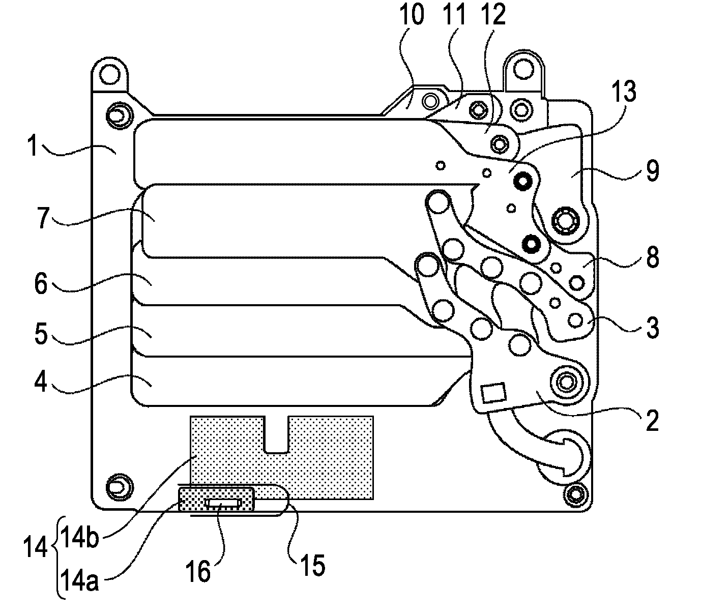
[0024]FIGS. 1 to 8 show a structure of a focal-plane shutter device, which corresponds to a shutter device according to the present invention. The focal-plane shutter device will be described as being installed in a digital single-lens reflex camera.

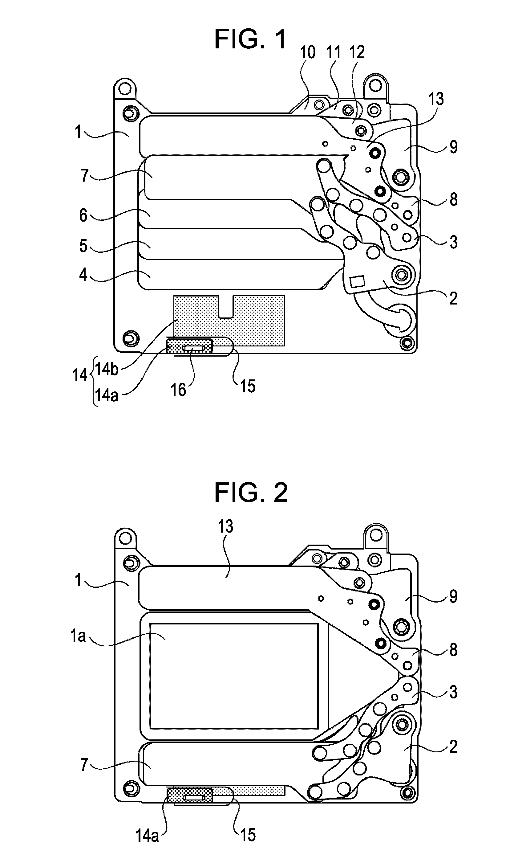
[0025]FIG. 1 is a front view of a shutter device in a state in which charging of a first curtain shutter blade unit (reference number is 4˜7) and a second curtain shutter blade unit (reference number is 10˜13) is completed. FIG. 2 is a front view of the shutter device in a state in which movement of the first curtain shutter blade unit f...


PUM


Abstract

A shutter device makes it possible to restrict bounding of a shutter blade using a shock-absorbing member when movement of the shutter blade is completed. In addition, the shutter device makes it possible to reduce production of dust that is produced when the shock-absorbing member and the shutter blade collide with each other. Examples of dust are wear powder and flake.

Description

BACKGROUND OF THE INVENTION[0001]1. Field of the Invention[0002]The present invention relates to a structure of a shutter device, and, more particularly, to a mechanism for preventing a shutter blade from bounding.[0003]2. Description of the Related Art[0004]In a related focal-plane shutter device, a shock-absorbing member for restricting bounding of a shutter blade is provided near a movement completion position of the shutter blade. When the shutter blade collides with the shock-absorbing member in a plane that is perpendicular to a movement direction of the shutter blade when the movement of the shutter blade is completed, shock generated by suddenly stopping the shutter blade is absorbed by the shock absorbing member, so that the bounding of the shutter blade occurring when the shutter blade is stopped can be restricted. Rubber is frequently used for the shock-absorbing member.[0005]When the collision between the shutter blade and the rubber is repeated, scraping of the rubber i...

Claims


Application Information

Patent Timeline
IPC IPC(8): G03B9/08
CPCG03B9/36
Inventor NISHIO, TETSUYA
Owner CANON KK
Why Eureka
Try Eureka