Thin-film forming apparatus and thin-film forming method

Inactive Publication Date: 2008-10-30
LAPIS SEMICON CO LTD
View PDF2 Cites 5 Cited by
  • Summary
  • Abstract
  • Description
  • Claims
  • Application Information

AI Technical Summary

Benefits of technology

[0014]It is one object of the present invention to provide a thin-film forming apparatus and a thin-film formin

Problems solved by technology

Although the normal pressure CVD apparatus is designed to remove particles and an unreacted film-forming gas through an exhaust duct, some of the particles and unreacted film-forming gas inev

Method used


Image

  • Thin-film forming apparatus and thin-film forming method
  • Thin-film forming apparatus and thin-film forming method
  • Thin-film forming apparatus and thin-film forming method

Examples


Embodiment Construction

[0031]An embodiment of the present invention will be described hereinafter in detail with reference to the drawings.

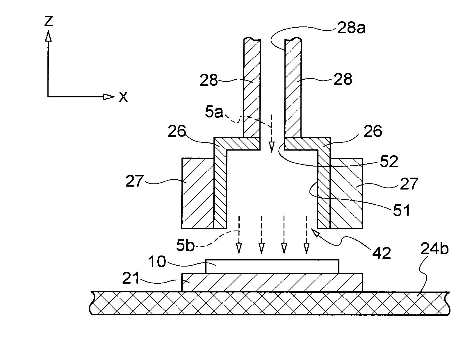
[0032]Referring to FIG. 2, a structure of a thin-film forming apparatus 20 according to one embodiment of the present invention will be described. The thin-film forming apparatus 20 is, for example, an O3(ozone)-TEOS(tetraethoxysilane:Si(OC2H5)4)-CVD apparatus.

[0033]The thin-film forming apparatus 20 includes a conveying device 24 that conveys a wafer 10 placed on a tray 21 from a loading portion 22 to an unloading portion 23. In the illustrated embodiment, the conveying device 24 is a belt conveyor unit having a pair of rollers 24a and a belt 24b. It should be noted that the conveying device 24 is not limited to a belt conveyor. For example, the conveying device 24 is a roller conveyor. It should also be noted that, depending on the type of the conveying device 24, the wafer 10 may directly be put on the conveying device 24 without the tray 21. An overhead cover 25 is...


PUM

PropertyMeasurementUnit
Flow rateaaaaaaaaaa
Widthaaaaaaaaaa
Heightaaaaaaaaaa

Abstract

A thin-film forming method of this invention forms a thin film on a wafer. This method is capable of improving the quality yield of wafers. The thin-film forming method includes the step of suctioning a flow of a film-forming gas from both sides of a conveyance path while conveying a wafer along the conveyance path. The conveyance path extends in a direction of passing through the gas flow.

Description

BACKGROUND OF THE INVENTION[0001]1. Field of the Invention[0002]The present invention relates to a thin-film forming apparatus and a thin-film forming method for applying a film-forming gas on a wafer to form a thin film thereon.[0003]2. Description of the Related Art[0004]A thin-film forming technology includes not only forming thin films but also realizing various high-order functions, such as an electrical function, an optical function and a mechanical function.[0005]The thin-film forming technology that realizes these high-order functions is an important technology in the semiconductor industry involving transistors. Particularly, importance of the thin-film forming technology is recognized as a process technology for creating a semiconductor circuit element. The reason for such recognition of the thin-film forming technology is that a thin film, which is formed in a semiconductor production process, remains as it is in the device structure, i.e., the thin film has a great influ...

Claims


Application Information

Patent Timeline
IPC IPC(8): C23C16/44
CPCC23C16/4412C23C16/45595H01L21/6776
Inventor KITAGAWA, TETSUYA
Owner LAPIS SEMICON CO LTD
Why Eureka
Try Eureka