Antenna and wireless network device having the same

a wireless network device and antenna technology, applied in the field of antennas, can solve the problems that traditional printed antennas cannot meet the needs of the vertical stand design achieve the effects of improving the radiation pattern of wireless network devices, enhancing gain value, and increasing antenna efficiency

Inactive Publication Date: 2008-10-30
CAMEO COMM
View PDF0 Cites 4 Cited by
  • Summary
  • Abstract
  • Description
  • Claims
  • Application Information

AI Technical Summary

Benefits of technology

[0008]A primary object of the present invention is to provide an antenna applied to a wireless network device, which is an embedded antenna for reducing the height thereof and improving the antenna radiation pattern thereof so as to increase the gain value on the vertical direction thereof and minimize the dead angle thereof.
[0009]A secondary object of the present invention is to provide an antenna, which is an improved Plated Inverted-F Antenna (PIFA) advantageous to manufacture the antenna and assemble the antenna into a wireless network device.
[0010]A third object of the present invention is to provide an antenna, which is provided with a monopole antenna and a pair of antennae of the present invention respectively disposed on two sides of the monopole antenna, so that the antenna is easy to manufacture without increasing the thickness of a MIMO wireless network device.
[0012]When the antenna is applied to a wireless network device according to the present invention, the wireless network device comprises a substrate, a control circuit, a ground portion, and at least one feed line. The substrate is made of dielectric material, and formed with at least one slot. The control circuit is formed on the substrate for providing a wireless transmission function. The ground portion is electrically grounded, and covers at least one portion of the substrate. The feed line passes through the ground portion, and is electrically connected to the control circuit for providing a wireless transmission and receiving function. When the antenna of the present invention is positioned in the slot, the side wall portion is connected to the sides and attached to an inner side of the slot, so that the locking wing portion is attached to a surface of the substrate. Meanwhile, the radiation member is spaced apart from the substrate with a height difference between the second height and the first height. Furthermore, the ground member is connected to the ground portion, and the free end of the signal member is connected to the feed line. Thus, the antenna of the present invention improves the radiation pattern of the wireless network device and enhances the gain value on the vertical direction thereof for considerably increasing the antenna efficiency.

Problems solved by technology

Apparently, the traditional printed antenna generates unwanted gain on the vertical direction of the Z axis, so that the traditional printed antenna can not satisfy the need of the vertical stand design of the wireless network devices.

Method used


Image

  • Antenna and wireless network device having the same
  • Antenna and wireless network device having the same
  • Antenna and wireless network device having the same

Examples


Embodiment Construction

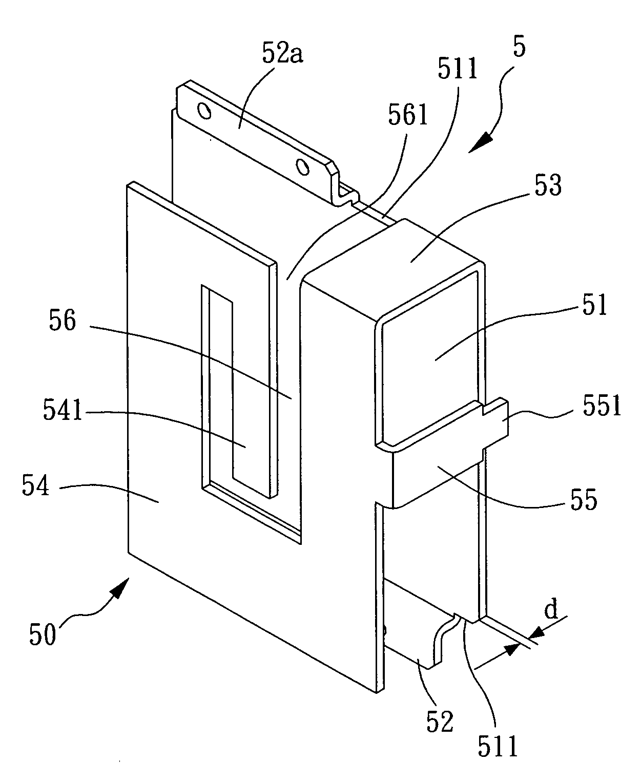
[0024]The present invention provides an antenna and a wireless network device having the same, the principle thereof is to apply a Plated Inverted-F Antenna (PIFA) to a MIMO wireless network device which is provided with a MIMO antenna unit with three antennae, wherein an intermediate antenna is selected from a monopole antenna, and two antennae disposed on two sides of the intermediate antenna are selected from PIFA antennae. Thus, the gain value on the vertical direction of an X-Y plane of the two sides of the intermediate antenna can be improved and enhanced, and the height of a radiation member within an internal circuit device can be minimized without increasing the thickness of the MIMO wireless network device.

[0025]Referring now to FIGS. 5, 6, and 7, a perspective view, a side view, and a front view of an antenna according to a preferred embodiment of the present invention are illustrated, respectively. As shown, the antenna designated by numeral 5 is a one-piece metal plate ...


PUM


Abstract

An antenna applied to a wireless network device comprises a base, a pair of embedded portions, and an antenna portion. The base has two sides opposite to each other. Each of the embedded portions has a side wall portion and a locking wing portion. The side wall portion is substantially vertical to the base and connected to the sides of the base, while the locking wing portion is connected to the side wall portion, substantially parallel to the base, and spaced apart from the base with a first height. The antenna portion is provided with a ground member, a radiation member, and a signal member. The ground member is substantially vertical to the base, connected to one of the two sides of the base, and spaced apart from the embedded portion with an interval. The radiation member is connected to the ground member, substantially parallel to the base, and spaced apart from the base with a second height. The signal member is connected to the radiation member, substantially vertical to the base, and formed with a free end separated from the base. When the antenna is positioned in at least one slot formed on a substrate of the wireless network device, the radiation member is spaced apart from the substrate with a height difference between the second height and the first height.

Description

BACKGROUND OF INVENTION[0001]1. Field of the Invention[0002]The present invention relates to an antenna, and more particularly to a Plated Inverted-F Antenna (PIFA) applied to a MIMO wireless network device and a wireless network device having the same.[0003]2. Description of the Prior Art[0004]Referring now to FIG. 1, an outline perspective view of a traditional wireless network device 10 is illustrated. Generally, the wireless network device 10 is provided with a body 11, an internal circuit device 12 formed in the body 11, a connector 13 formed on a first end of the body 11 for connecting to an external host (not shown), and an antenna signal transmitter / receiver 14 formed on a second end of the body 11 opposite to the first end thereof. Broadly, the antenna signal transmitter / receiver 14 has an outer housing made of non-metal material. When the wireless network device 10 is connected to the external host, the antenna signal transmitter / receiver 14 must be exposed out of the exte...

Claims


Application Information

Patent Timeline
Patent Type & Authority Applications(United States)
IPC IPC(8): H04M1/00
CPCH01Q1/243H01Q9/0421H01Q21/28
Inventor CHEN, YU REN
Owner CAMEO COMM
Why Eureka
Try Eureka