Power unit for motorcycle

a power unit and motorcycle technology, applied in the direction of machines/engines, gearing details, hoisting equipment, etc., can solve the problems of not only the structure complicating the configuration of the oil passage, and achieve the effect of increasing the diameter of the pulley sha

Inactive Publication Date: 2008-10-30
HONDA MOTOR CO LTD
View PDF5 Cites 13 Cited by
  • Summary
  • Abstract
  • Description
  • Claims
  • Application Information

AI Technical Summary

Benefits of technology

[0007]The present invention has been made in view of such circumferences and it is an object of an embodiment of the present invention to provide a power unit for a motorcycle that enables a supply of working

Problems solved by technology

However, such a structure not only complicates the oil passage configuration but also needs to set the outside d

Method used


Image

  • Power unit for motorcycle
  • Power unit for motorcycle
  • Power unit for motorcycle

Examples


Embodiment Construction

[0029]An embodiment of the present invention will hereinafter be described with reference to the accompanying drawings.

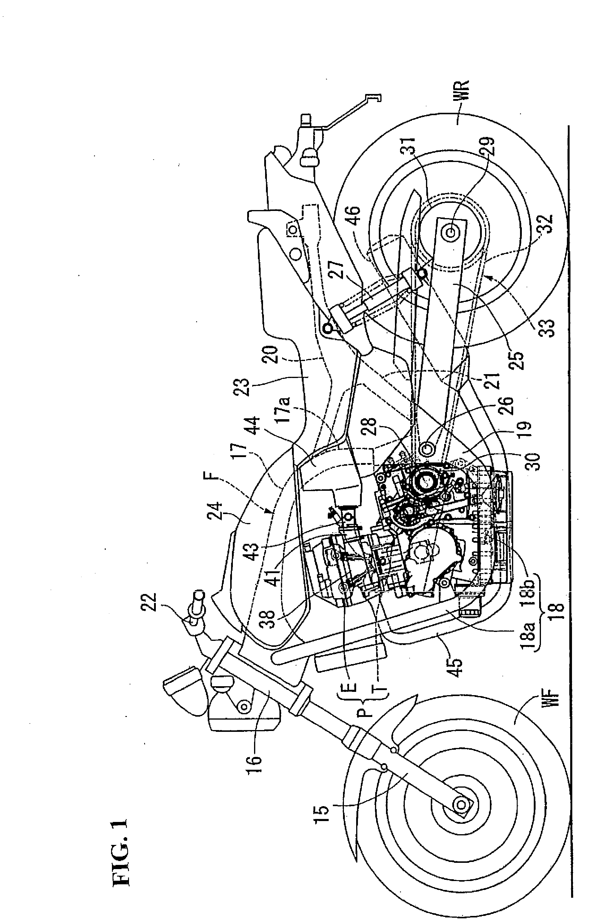
[0030]FIGS. 1 to 14 illustrate an embodiment of the present invention. It is to be noted that the front and rear and the left and right in the embodiment refer to respective directions in the state where the motorcycle faces the front of the traveling direction thereof.

[0031]Referring first to FIG. 1, a body frame F of the motorcycle includes a head pipe 16, a main frame 17, a pair of left and right down frames 18, pivot plates 19, a pair of left and right seat rails 20 and a pair of left and right connection frames 21. The head pipe 16 steerably supports a front fork 15 which has a lower end rotatably supporting a front wheel WF. The main frame 17 extends rearward from the head pipe 16, bends therefrom and extends downward to form a hanging portion 17a at the rear portion thereof. The down frame 18 has a slant portion 18a which slants rearward downwardly from the h...


PUM


Abstract

A motorcycle including a power transmission device including a continuously variable transmission having a belt wound around a drive pulley and around a driven pulley and a hydraulically-operated clutch provided on at least one of a drive pulley shaft and a driven pulley shaft and an internal combustion engine wherein a supply of working oil to the clutch and of lubricating oil to a continuously variable transmission is enabled while avoiding a complication of an oil passage configuration and an increase in the diameter of the pulley shaft. A clutch control oil passage directs working oil to a clutch and a lubricating oil passage directs lubricating oil to a continuously variable transmission are provided in the particular pulley shaft on which the clutch is provided, so as to be coaxial with each other and be axially isolated from each other.

Description

CROSS-REFERENCE TO RELATED APPLICATIONS[0001]The present application claims priority under 35 USC 119 to Japanese Patent Application No. 2007-115802 filed on Apr. 25, 2007 the entire contents of which are hereby incorporated by reference.BACKGROUND OF THE INVENTION[0002]1. Field of the Invention[0003]The present invention relates to a power unit for a motorcycle including an internal combustion engine and a power transmission device that includes a continuously variable transmission and a hydraulically-operated clutch. The transmission includes a drive pulley provided on a drive pulley shaft adapted to receive rotational power transmitted from the engine, a driven pulley provided on a driven pulley shaft having an axis parallel to the drive pulley shaft and a belt wound around the drive pulley and around the driven pulley. The clutch is provided on at least one of the drive pulley shaft and the driven pulley shaft.[0004]2. Description of Background Art[0005]A power unit for a motorc...

Claims


Application Information

Patent Timeline
IPC IPC(8): F16H59/00
CPCF02B41/00F02B75/02
Inventor MITSUBORI, TOSHIMASAHARA, ERIKA
Owner HONDA MOTOR CO LTD
Why Eureka
Try Eureka