Power unit

a power unit and motor technology, applied in the direction of battery/cell propulsion, electric devices, gearing, etc., can solve the problems of dragging losses, degrading the efficiency of the whole power unit, and high rotational speed of the second rotary motor, so as to reduce the rotary motor and enhance the efficiency of the power unit

Active Publication Date: 2008-10-30
HONDA MOTOR CO LTD
View PDF28 Cites 49 Cited by
  • Summary
  • Abstract
  • Description
  • Claims
  • Application Information

AI Technical Summary

Benefits of technology

[0008]It is an object of the present invention to provide a power unit that is capable of downsizing rotary motors and enhancing the efficiency of the power unit.

Problems solved by technology

Further, for the same reason, in the latter case in which the rotational speeds of the first and second rotary motors become too high, dragging losses are caused due to dragging of the first and second rotary motors.
This results in the degraded efficiency of the whole power unit.
Furthermore, in the conventional power unit, in changing the rotational speed of the engine as described above, particularly during a high-speed operation of the vehicle in which the rotational speed of the drive wheels is higher than that of the engine, the rotational speed of the second rotary motor becomes very high due to the above-described connection relationship, which sometimes causes dragging losses.
In this case, however, the best fuel economy of the engine cannot be obtained, and the efficiency of the whole power unit is degraded after all.

Method used


Image

  • Power unit
  • Power unit
  • Power unit

Examples


Embodiment Construction

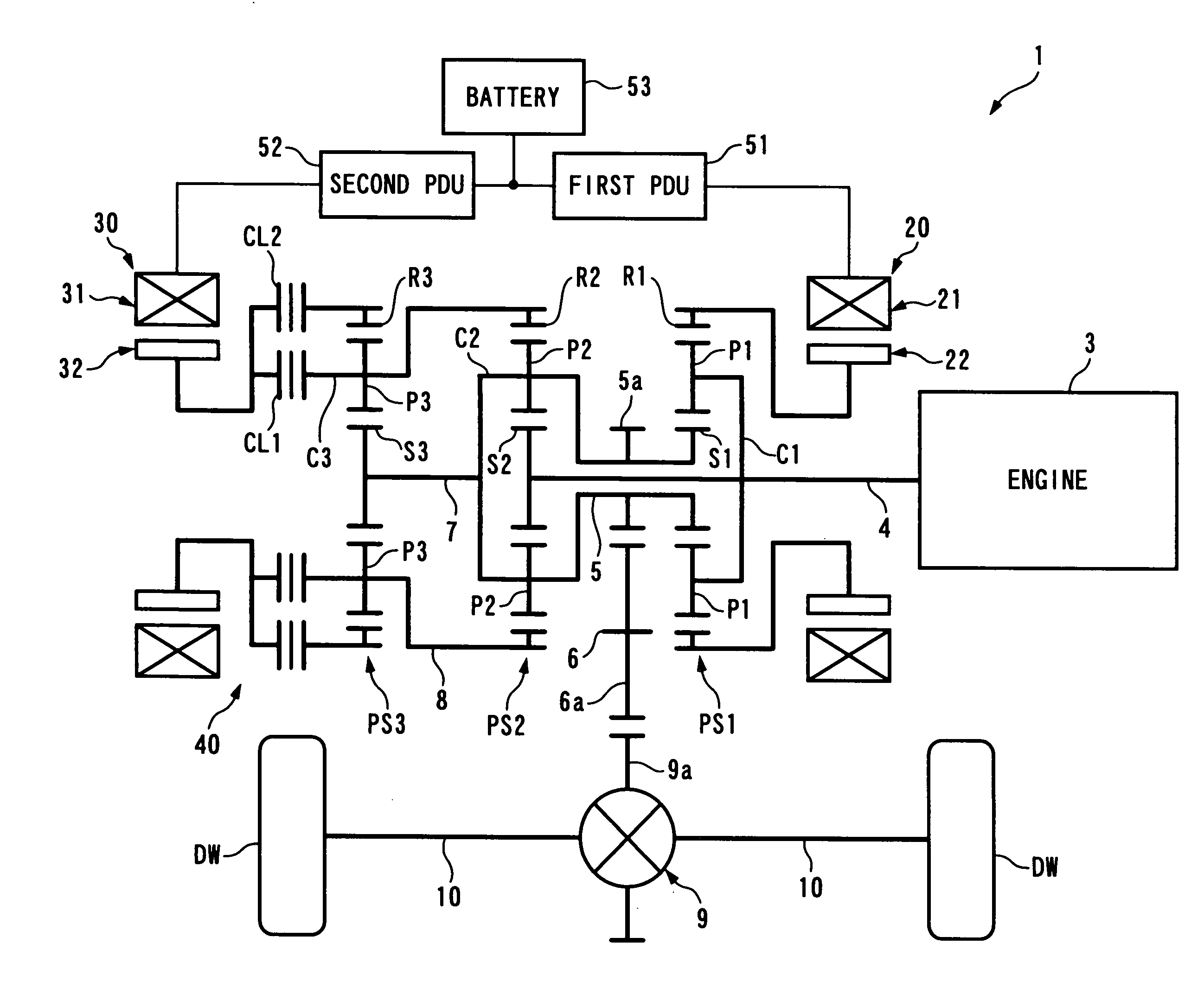
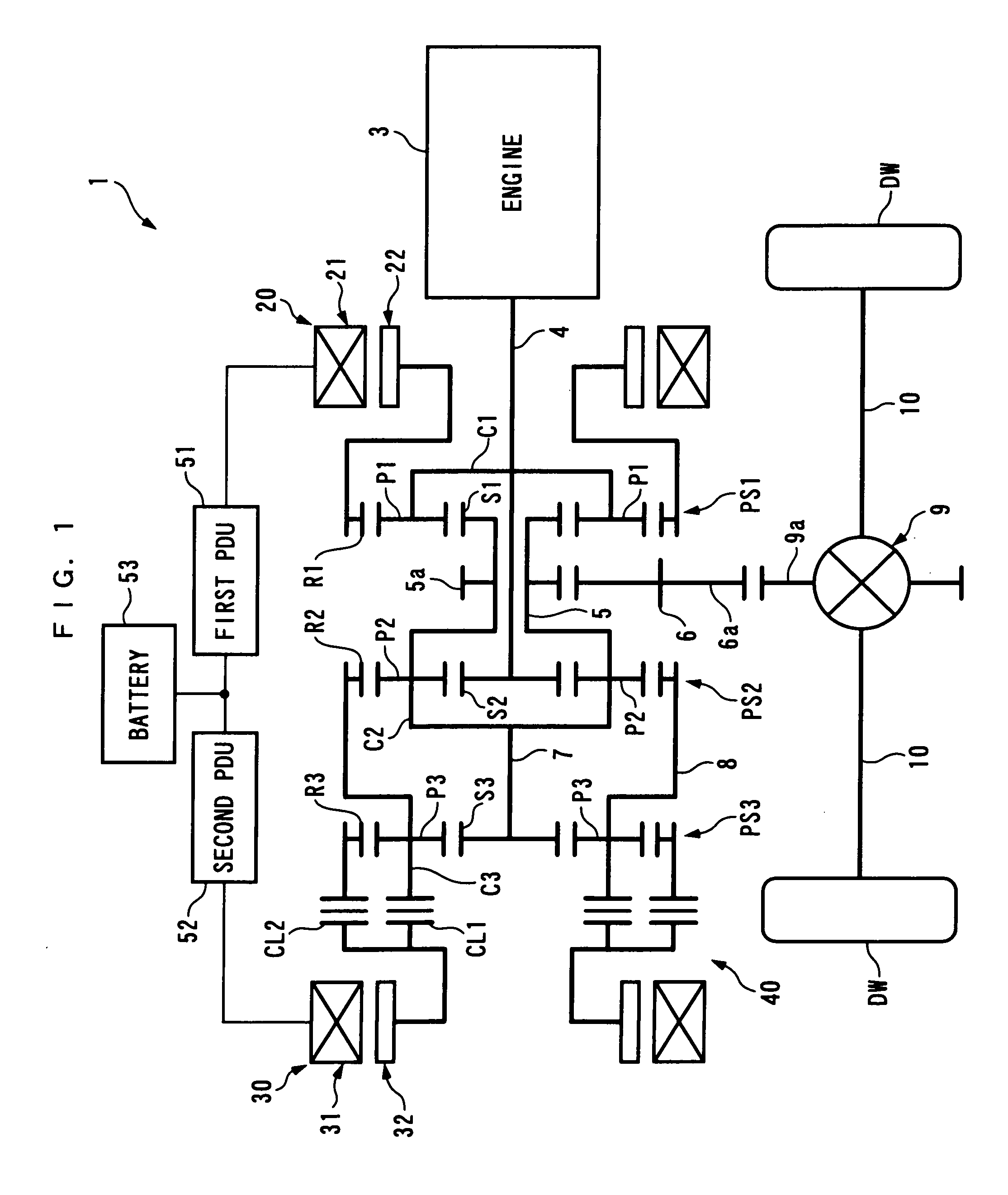
[0056]The invention will now be described in detail with reference to the drawings showing preferred embodiments thereof. FIGS. 1 and 2 schematically show a power unit 1 according to a first embodiment of the present invention. The power unit 1 is for driving left and right drive wheels DW and DW (driven member) of a vehicle, not shown, and is, as shown in FIG. 1, comprised of an internal combustion engine 3 (prime mover), a first rotary motor 20, a second rotary motor 30, which are power sources, and a first planetary gear unit PS1 (power transmission mechanism, one of a plurality of planetary gear units) and a second planetary gear unit PS2 (power transmission mechanism, one of the plurality of planetary gear units), a transmission 40, a differential gear mechanism 9, and left and right drive shafts 10 and 10, for transmitting a driving force to the drive wheels DW and DW. The internal combustion engine (hereinafter simply referred to as “the engine”) 3 is an gasoline engine, for ...


PUM


Abstract

A power unit capable of downsizing rotary motors and enhancing efficiency of the power unit. In first and second planetary gear units, a first ring gear, a first carrier, a second sun gear, a first sun gear, a second carrier, and a second ring gear, capable of transmitting power to each other, are configured such that they satisfy a collinear relationship and are in a line in a collinear chart. The first carrier and the second sun gear are connected to a prime mover, and the first sun gear and the second carrier are connected to drive wheels. The first and second ring gears are connected to the first and second rotary motors, respectively. The first and second rotary motors are connected to each other. A transmission is disposed at least between the first rotary motor and the first ring gear or between the second rotary motor and the second ring gear.

Description

BACKGROUND OF THE INVENTION[0001]1. Field of the Invention[0002]The present invention relates to a power unit for driving a driven member, and more particularly to a power unit having an internal combustion engine and rotary motors as power sources.[0003]2. Description of the Related Art[0004]Conventionally, as a power unit of this kind, one disclosed e.g. in Japanese Laid-Open Patent Publication (Kokai) No. 2002-281607 is known. This power unit is for driving drive wheels of a vehicle, and is provided with an internal combustion engine, a first rotary motor, and a second rotary motor, which are power sources, a first planetary gear unit and a second planetary gear unit, which are of a general type. A carrier of the first planetary gear unit and a sun gear of the second planetary gear unit are directly connected to each other without using a gear or a transmission and are directly connected to the engine. A ring gear of the first planetary gear unit and a carrier of the second plane...

Claims


Application Information

Patent Timeline
Patent Type & Authority Applications(United States)
IPC IPC(8): F16H37/08B60L50/16
CPCB60K1/02Y02T10/6239B60K6/445B60L7/14B60L11/123B60L11/14B60L2220/16B60L2240/421B60W10/02B60W10/08B60W20/00B60W2510/0685B60W2510/081B60W2510/244B60W2520/10B60W2540/10B60W2710/0644B60W2710/081F16H3/727F16H2037/102F16H2037/104F16H2037/106F16H2200/201Y02T10/6217Y02T10/646Y02T10/7077Y02T10/648B60K6/365B60K2006/268B60L50/16B60L50/61Y02T10/62Y02T10/64Y02T10/70Y02T10/7072B60W10/115B60W20/40
Inventor ABE, NORIYUKIAKUTSU, SHIGEMITSU
Owner HONDA MOTOR CO LTD
Why Eureka
Try Eureka