Locking Device

a technology of locking device and sealing element, which is applied in the direction of mechanical control device, process and machine control, instruments, etc., can solve the problems of high cost, low sealing force, and difficulty in ensuring the minimum pressure force along the sealing element, so as to achieve simple and reliable sealing of the lock

Active Publication Date: 2008-11-06
APPLIED MATERIALS INC
View PDF6 Cites 7 Cited by
  • Summary
  • Abstract
  • Description
  • Claims
  • Application Information

AI Technical Summary

Benefits of technology

[0006]The task of the present invention is to devise a generic lock device with which simple and reliable sealing of a lock opening arranged in a wall can be achieved.
[0007]According to this invention, a first magnetic device is provided in an area of a counterplate in a lock device for a lock opening arranged in a wall between the first and second receptacle, with a blocking device arranged in the interior of the first receptacle and the counterplate assigned to the blocking device. A second magnetic device assigned to the first magnetic device is provided in an area of the blocking device. To close and / or open the lock opening, a positive and / or negative pressure force can be created between the blocking device and the counterplate by means of the first and second magnetic devices. According to the invention, the pressure force that produces sealing essentially acts locally at the sites at which sealing occurs. Because of this principle, no deformation of force-transferring design elements, such as a shaft or the like between the force generation site and the sealing site therefore occurs. Overall, the design elements can therefore be made very thin, preferably in a light-weight design. This has the additional advantage that only limited weights need be moved and a very dynamic system with short closing and opening times can therefore be achieved. The two receptacles are preferably vacuum chambers.
[0008]At least one of said magnetic devices has at least one switchable magnetic coil to produce a magnetic field; a closing and / or opening force can be generated or interrupted in a particularly simple manner.

Problems solved by technology

Problems frequently occur in lock valves of vacuum chambers, especially for so-called in-line installations for substrate coating, during sealing of the lock-valve flap with respect to the receptacle.
The consequence of the resulting deformations is non-uniform pressure of the lock-valve flap on an elastic sealing element enclosing the lock opening, which means that the minimum pressure force necessary for reliable sealing is not ensured along the sealing element at all locations.
A common, but demanding and costly concept to guarantee sufficient sealing consists of using components of very large dimensions, with which sufficiently high torque and corresponding pressure can be applied.
However, it has been found that with this known lock valve, the highest sealing requirements cannot be achieved, because the required sealing ring is stressed too unevenly in the closed state and the sealing plate and drive shaft bend too much in the closed state.
This problem occurs, in particular, if the valve plate has an extreme width / length ratio, as is typically required in in-line installations for flat large-surface substrates.
A drawback of this lock is the high design expense and the difficulty of excluding particle contamination due to torsion of the valve plate.
Since the sealing element is connected to a pivot axis, it is difficult, in this already known valve device, to guarantee uniform pressure along the opening course.
This lock valve can therefore only withstand the pressure difference between the vacuum and atmospheric pressure, if the valve arranged at atmospheric pressure acts to support the closing force in the closure direction of the valve flap.
The flap element is disconnected from the pivot bearing by an expensive flexible connection, for example spring-loaded.

Method used


Image

  • Locking Device
  • Locking Device
  • Locking Device

Examples


Embodiment Construction

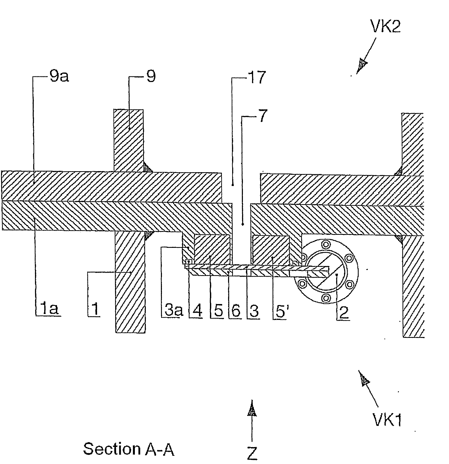
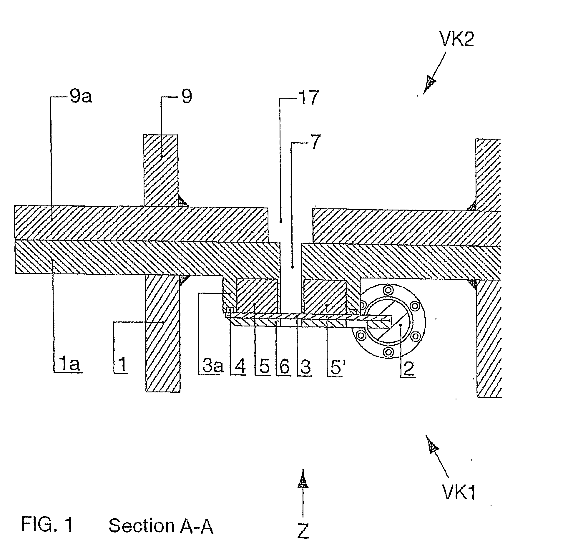
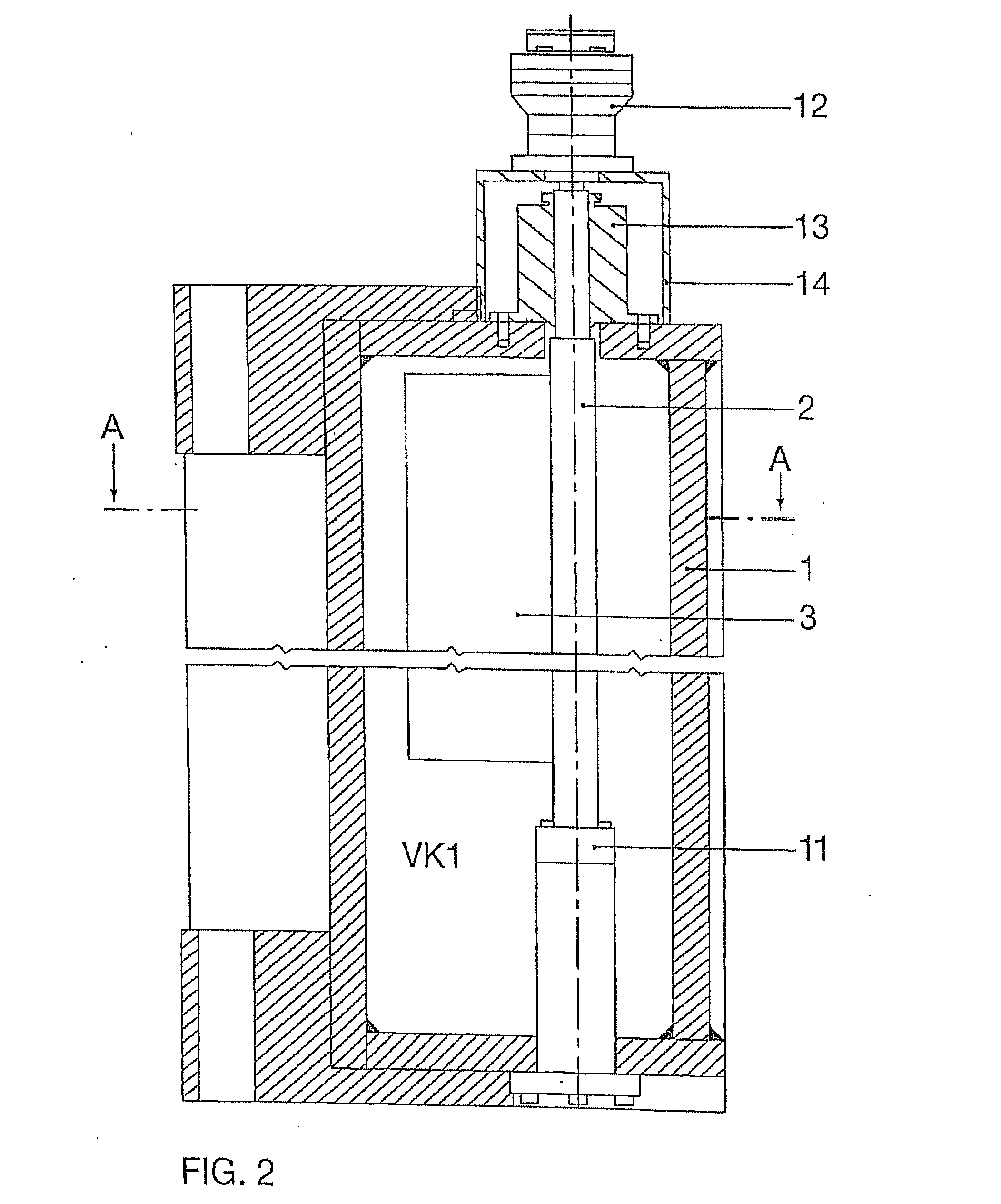
[0023]A horizontal section A-A and a vertical section perpendicular to A-A of a lock device according to the invention for a lock opening arranged in a wall between a first and a second receptacle are shown in FIGS. 1 and 2. The receptacles are vacuum chambers. This type of lock device is advantageously used in so-called in-line systems for the production of substrates for flat displays. Typically, such substrates are about 1 mm thick, rectangular, with a size of 1000×1200 mm or more. The substrates are guided suspended in the in-line system along a linear or U-shaped path through a number of vacuum chambers, which can be separated from each other by locks. Because of the substrate dimensions, typical lock openings are characterized by an extreme length / width ratio. However, it is understood that the lock device according to the invention can also be used for other lock-opening profiles. The lock device according to the invention can be made from thin-walled and light components, an...


PUM


Abstract

The invention relates to a locking device for a lock opening which is arranged in a wall between a first and a second recipient, said lock opening comprising a blocking element, which is arranged in the inner chamber of the first recipient, and a counter-plate which is associated with the blocking element. A first magnet device is provided in an area of the counter-plate and a second magnet device, which is associated with the first magnet device, is provided in the region of the blocking element. In order to close and / or open the locking device by means of the first and second magnet device, a positive and / or negative contact pressure can be produced between the blocking element and the counter-plate.

Description

TECHNICAL FIELD OF THE INVENTION[0001]The invention relates to a lock device.BRIEF DISCUSSION OF RELATED ART[0002]Problems frequently occur in lock valves of vacuum chambers, especially for so-called in-line installations for substrate coating, during sealing of the lock-valve flap with respect to the receptacle. An important influencing factor in lock valves with lock-valve flaps that can be pivoted is deformation, especially twisting of the pivot shaft and the lock-valve flap when the flap presses against the receptacle in the closed state of the lock valve. The consequence of the resulting deformations is non-uniform pressure of the lock-valve flap on an elastic sealing element enclosing the lock opening, which means that the minimum pressure force necessary for reliable sealing is not ensured along the sealing element at all locations. A common, but demanding and costly concept to guarantee sufficient sealing consists of using components of very large dimensions, with which suff...

Claims


Application Information

Patent Timeline
Patent Type & Authority Applications(United States)
IPC IPC(8): F16K51/02F16K1/20F16K3/10F16K31/08H01L21/00H01L21/677
CPCF16K31/082F16K31/084F16K51/02F16K1/2007F16K1/2028F16K1/2057H01L21/67772Y10T70/5615Y10T137/7069F16K3/10H01L21/00
Inventor RODER, MARIOMULLER, ALEXANDERCASPARI, ANDREASVOGT, THOMAS
Owner APPLIED MATERIALS INC
Why Eureka
Try Eureka