Eureka AIR delivers breakthrough ideas for toughest innovation challenges, trusted by R&D personnel around the world.

Hydraulic unit for a heating or air-conditioning system

a technology of heating or air-conditioning system and construction unit, which is applied in the direction of fluid heaters, heating types, lighting and heating apparatus, etc., can solve the problem of difficult temperature regulation of the heating medium

Active Publication Date: 2020-01-16
GRUNDFOS HLDG
View PDF0 Cites 1 Cited by
  • Summary
  • Abstract
  • Description
  • Claims
  • Application Information

AI Technical Summary

Benefits of technology

The invention is a hydraulic connection assembly that includes a mixing valve integrated into a pump housing for a compact and cost-effective manufacture and assembly. The movable valve element of the mixing valve is connected to a drive motor outside the housing via a pivoting actuating lever, which extends through an elastic seal. This design eliminates the need for a dynamic seal in the valve housing and allows for a simple and reliable sealing. The valve element has two valve surfaces that can be moved to change the flow cross sections, and the hydraulic connection elements are connected to at least one mechanical supporting element to transmit mechanical forces onto the supporting element and keep them remote from the hydraulic flow paths. The technical effects of the invention are a compact construction, cost-effectiveness, and reliable and efficient hydraulic connection.

Problems solved by technology

The disadvantage of these known construction units for heating facilities is the fact that a temperature regulation for the temperature of the heating medium is extremely difficult.
As a rule, this is only possible by way of adapting the output of the heat source.

Method used


Image

  • Hydraulic unit for a heating or air-conditioning system
  • Hydraulic unit for a heating or air-conditioning system
  • Hydraulic unit for a heating or air-conditioning system

Examples


Embodiment Construction

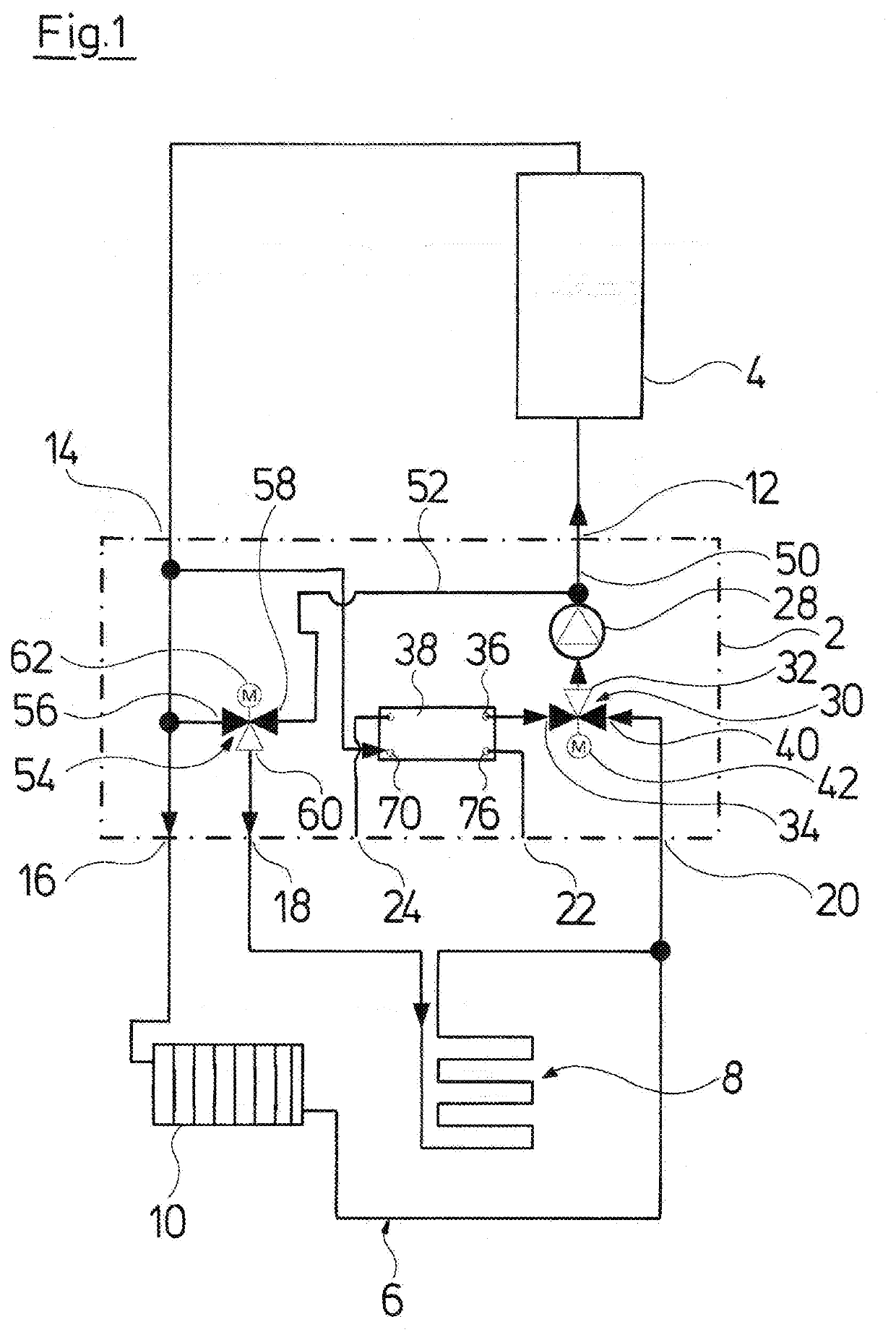
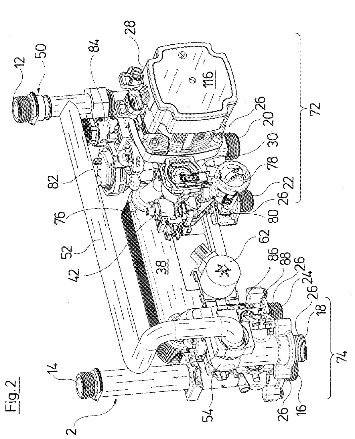
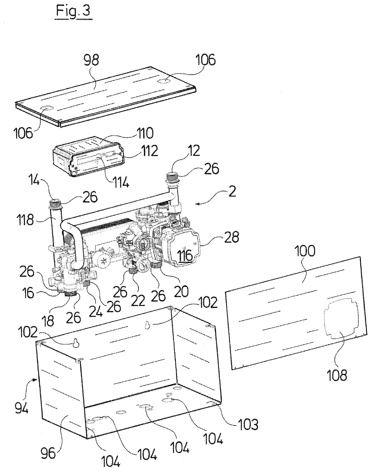
[0046]Referring to the drawings, FIG. 1 shows a heating facility which comprises a hydraulic construction unit 2 according to the invention, a heat source in the form of a primary heat exchanger 4 as well as two heating circuits 6 and 8. The heating circuit 6 is thereby a heating circuit which runs through radiators 10 (only one is represented schematically in the figure), whereas the heating circuit 8 is a heating circuit which forms a floor heating. Thereby, it is to be understood that the heating circuit 8 in turn can be subdivided into several floor heating circuits. The primary heat exchanger 4 in particular is part of a gas heating boiler. The primary heat exchanger 4 and the hydraulic construction unit 2 as a whole can be integrated into a compact heating facility, in particular into a gas heating facility. The hydraulic construction unit 2 thereby integrates all essential hydraulic components which are necessary for the operation of the heating facility.

[0047]The hydraulic c...


PUM


Abstract

A hydraulic construction unit for a heating facility or air-conditioning facility, includes a return connection (20) and a first feed connection (16) for a heating circuit (6), with a heat source outlet (12) fluid conducting connected to the return connection. A heat source inlet (14) is fluid conducting connected to the first feed connection and to a circulation pump assembly (28) in a flow path between the return connection and the heat source outlet (12) or in a flow path between the heat source inlet and the first feed connection. A second feed connection (18) for a second heating circuit (8), is fluid conducting connected to the heat source inlet and to the return connection. A mixing valve (54) is arranged in a flow path from the heat source inlet to the second feed connection and / or in a flow path from the return connection to the second feed connection.

Description

CROSS REFERENCE TO RELATED APPLICATIONS[0001]This application is a United States National Phase Application of International Application PCT / EP2018 / 052425 filed Jan. 31, 2018, and claims the benefit of priority under 35 U.S.C. § 119 of European Application 17 155 234.2, filed Feb. 8, 2017, the entire contents of which are incorporated herein by reference.TECHNICAL FIELD[0002]The invention relates to a hydraulic construction unit for a heating facility or an air-conditioning facility, with at least one pump assembly.TECHNICAL BACKGROUND[0003]Such a construction unit or housing unit for a heating facility is known for example from EP 2 397 777 A1. This construction unit comprises a circulation pump for delivering the heating medium, as well as in particular a heat exchanger for heating service (domestic) water. A switch-over valve is also provided, in order to switch the circuit for the heating medium between the mentioned heat exchanger and a connected heating circuit. The pump assem...

Claims


Application Information

Patent Timeline
IPC IPC(8): F24D19/10F24H9/14F24D3/02
CPCF24H9/144F24D19/1066F24D19/1033F24D3/02F24D2220/0235
Inventor BLAD, THOMASMØNSTER, PETER
Owner GRUNDFOS HLDG
Why Eureka
Eureka Blog
Learn More