Code-spurting marking machine jet printing head

A technology of marking machine and printing head, applied in printing and other directions, can solve the problems that the controller of the inkjet printer cannot adapt, the size of the printing fonts is different, and the printing effect is not beautiful, and achieves a simple structure and simple sealing. Reliable, easy-to-manufacture results

Active Publication Date: 2016-04-20
FUZHOU JUZHONGXIN ELECTRONICS CO LTD
View PDF5 Cites 2 Cited by
  • Summary
  • Abstract
  • Description
  • Claims
  • Application Information

AI Technical Summary

Problems solved by technology

Since the movement space of the solenoid valve of the printing head is very limited 0.1-0.3mm, even a small change will cause the change of the movement space of the solenoid valve. The rubber has the influence of fatigue resistance and elastic deformation, resulting in the change of the size of the printing point during printing. , the printing font size is different, making the printing effect unsightly and defective
[0003] In addition, the existing inkjet inkjet printer nozzles used in the market are all single-row multi-nozzle structures; there is also a patent number: 2011201876787, and the patent name is: high-resolution valve type inkjet printing head, This is an inkjet printer nozzle with a multi-nozzle structure arranged in a staggered arrangement. Although it breaks through the problem of a large ink dot pitch in a single-row nozzle structure and achieves a smaller ink dot pitch, its structure is complex and existing inkjet printers Machine controllers are unable to adapt, the controller needs to be redeveloped, the cost is high, and it is difficult to realize in practical applications

Method used


Image

  • Code-spurting marking machine jet printing head
  • Code-spurting marking machine jet printing head
  • Code-spurting marking machine jet printing head

Examples


Embodiment Construction

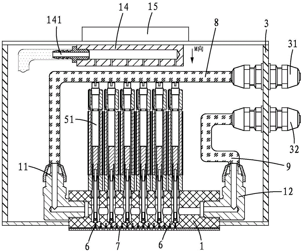
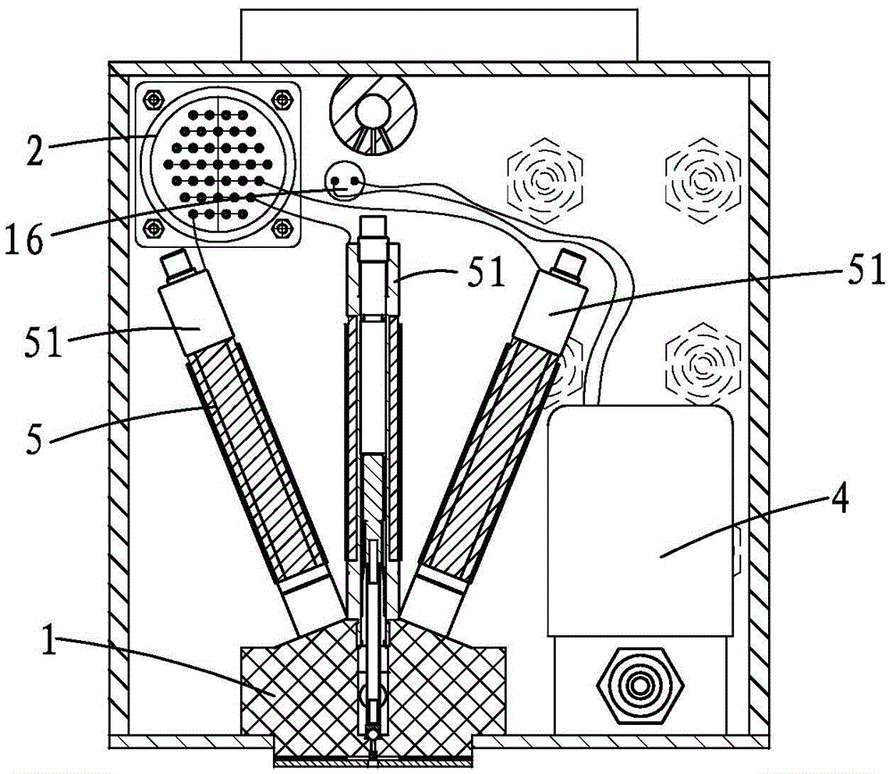
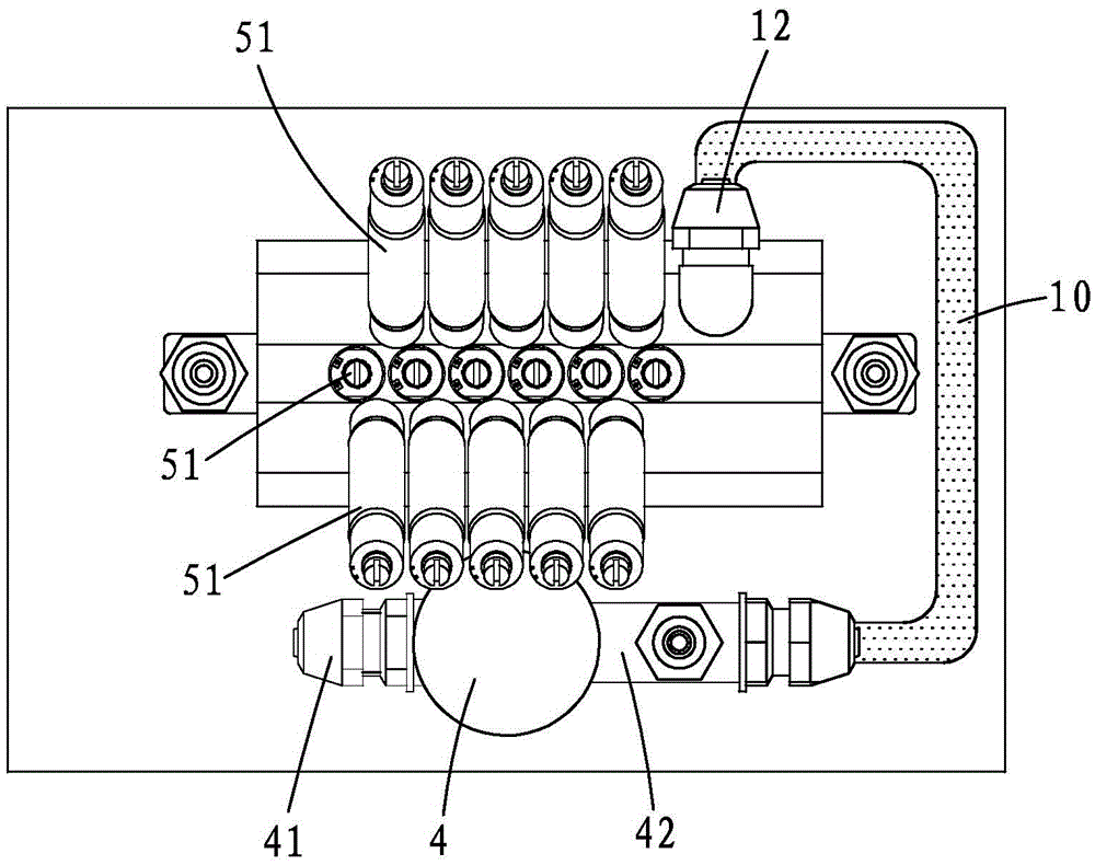
[0021] see Figure 1 to Figure 5 As shown, a jet printing head of a coding and marking machine of the present invention includes a staggered cavity seat 1, a 37-core aviation connector 2, a housing 3, a single-way solenoid valve 4 and multiple sets of solenoid valve assemblies 5. The solenoid valve assembly 5 includes three solenoid valves 51 arranged in a staggered cavity seat, and the three solenoid valves 51 are arranged intersecting, and the three solenoid valves 51 form a trident shape; each solenoid valve 51 Both are connected with 37-core aviation joints 2; the left and right ends of the staggered cavity seat 1 are respectively provided with a first elbow joint 11 and a second elbow joint 12, and the first elbow joint 11 and the second elbow joint 12 run through the The staggered cavity seat 1 is connected, the bottom of the staggered cavity seat 1 is provided with a plurality of jewel nozzles 6, and the number of jewel nozzles 6 is the same as that of the solenoid valv...


PUM


Abstract

The invention provides a code-spurting marking machine jet printing head, comprising a staggered cavity seat, a 37 core aviation joint, a housing, a single channel solenoid valve and a plurality of sets of solenoid valve modules. The solenoid valve modules comprise three solenoid valve arranged in the staggered cavity seat; left and right ends of the staggered cavity seat are respectively provided with a first bent sub and a second bent sub. The sidewall of the housing is provided with a first separator plate joint, a second separator plate joint, a third separator plate joint and a fourth separator plate joint. The first bent sub is in connection with the first separator plate joint through an ink incoming tube, and the second bent sub is in connection with the second separator plate joint through an ink discharge tube; the single channel solenoid valve is arranged in the housing. The code-spurting marking machine jet printing head can guarantee stable and reliable operation in any medium, normally and stably operate even using heavy pigment ink such as oil paint under hostile environments, reduce machine failure rates, and improve equipment stability and reliability.

Description

technical field [0001] The invention relates to the technical field of automatic marking equipment, in particular to a printing head of a coding and marking machine. Background technique [0002] At present, the existing inkjet printheads on the market print in heavy pigment ink, high corrosion, high dust and harsh on-site environments, which are prone to clogging, ink dot deflection, ink dot size changes randomly, and residual ink on the surface of the nozzle hole. The expansion of the sealing rubber after soaking in the solvent causes the valve stroke to change. In the use of dye-based inks, there are the above-mentioned defects. When using pigment inks, it is very easy to block the ink dots of different sizes, and when it is serious, it will stick to death and fail to work. For example, the patent is used for the nozzle of the large-character inkjet printer, see the patent No. 2012203021769, the title is: "A nozzle for the large-character inkjet printer" Chinese patent, ...

Claims


Application Information

Patent Timeline
Patent Type & Authority Applications(China)
IPC IPC(8): B41J2/14
CPCB41J2/14
Inventor 李宁
Owner FUZHOU JUZHONGXIN ELECTRONICS CO LTD
Why Eureka
Try Eureka