Flow Rate Switching Type Flow Divider

a flow divider and flow rate technology, applied in the direction of valve operating means/releasing devices, process and machine control, instruments, etc., can solve the problems of loss or increase of hydraulic circuit pressure, destabilization of control flow rate, and long second flow path, so as to simplify the circuit structure

Inactive Publication Date: 2008-11-06
TOYOTA IND CORP +1
View PDF7 Cites 17 Cited by
  • Summary
  • Abstract
  • Description
  • Claims
  • Application Information

AI Technical Summary

Benefits of technology

[0007]It is an object of the present invention to provide a flow rate switching type flow divider prevented from being lengthened in the axial direction of the spool so as to enable miniaturization while simplifying the circuit structure.

Problems solved by technology

These restrictions may cause loss or increase of pressure in the hydraulic circuit and destabilize the control flow rate.
Thus, the second flow path is long and extends in a complicated manner.

Method used


Image

  • Flow Rate Switching Type Flow Divider
  • Flow Rate Switching Type Flow Divider
  • Flow Rate Switching Type Flow Divider

Examples


Embodiment Construction

[0016]A preferred embodiment of the present invention will now be described hereinafter with reference to the drawings. The flow rate switching type flow divider of the present invention may be widely used for applications in which fluid from a pump is distributed to a priority flow circuit at a predetermined flow rate and to a surplus flow circuit.

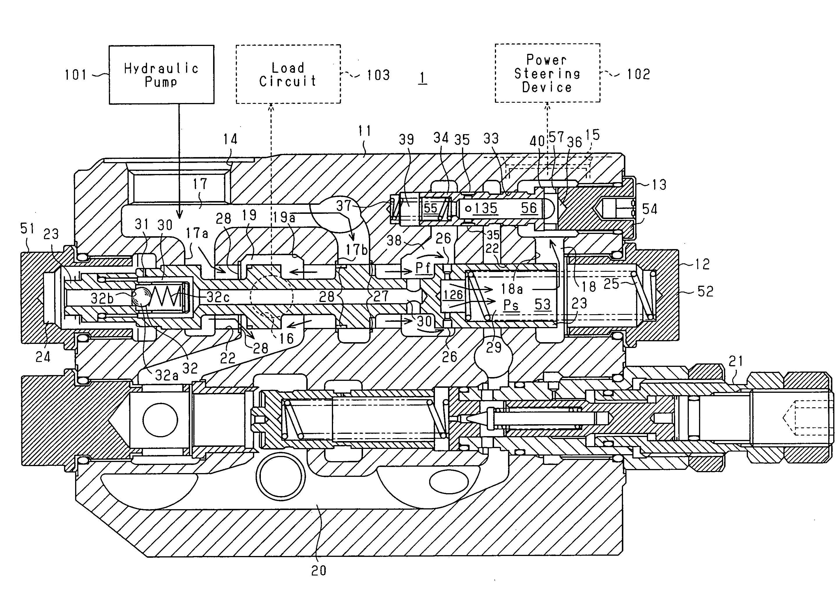
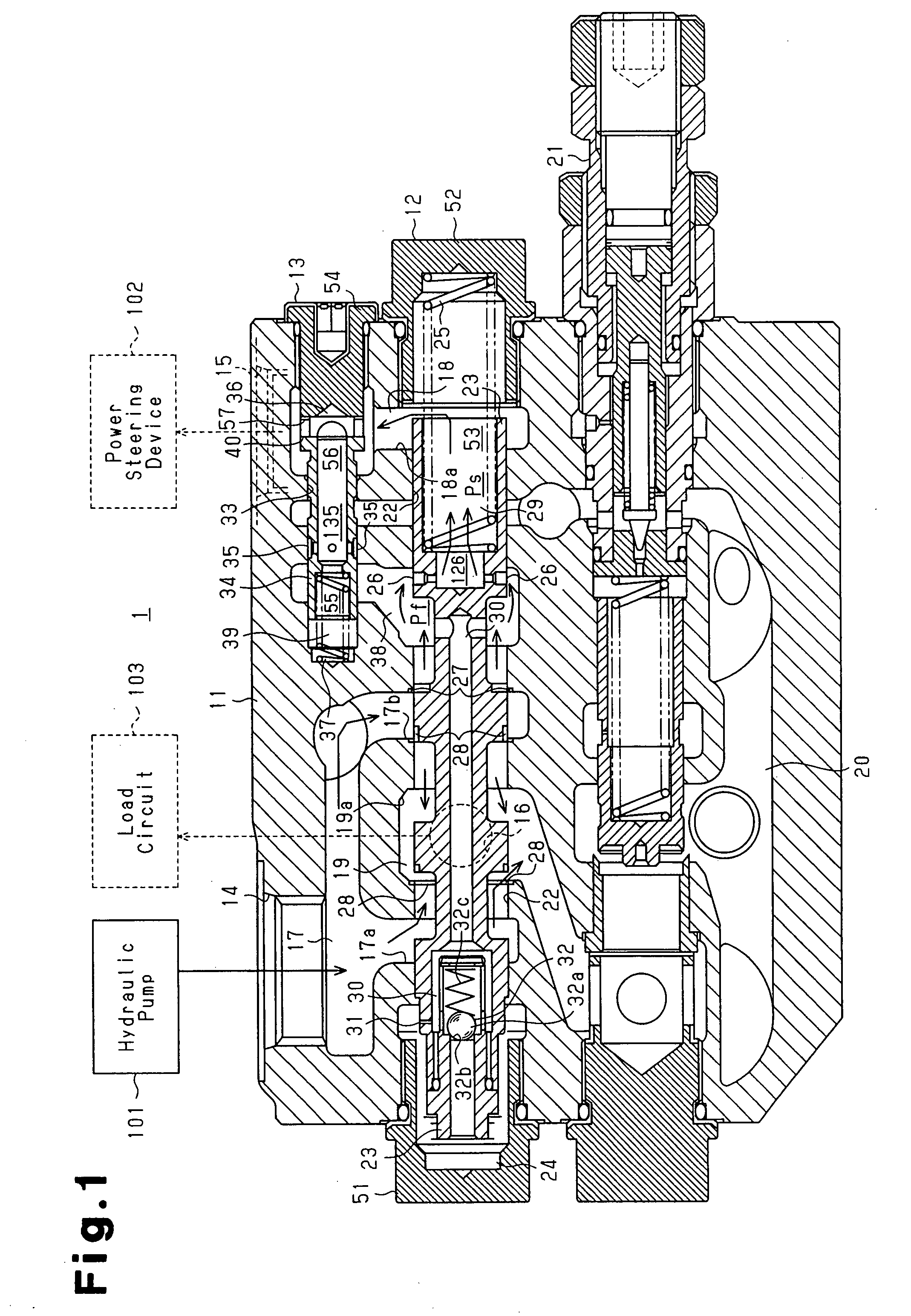
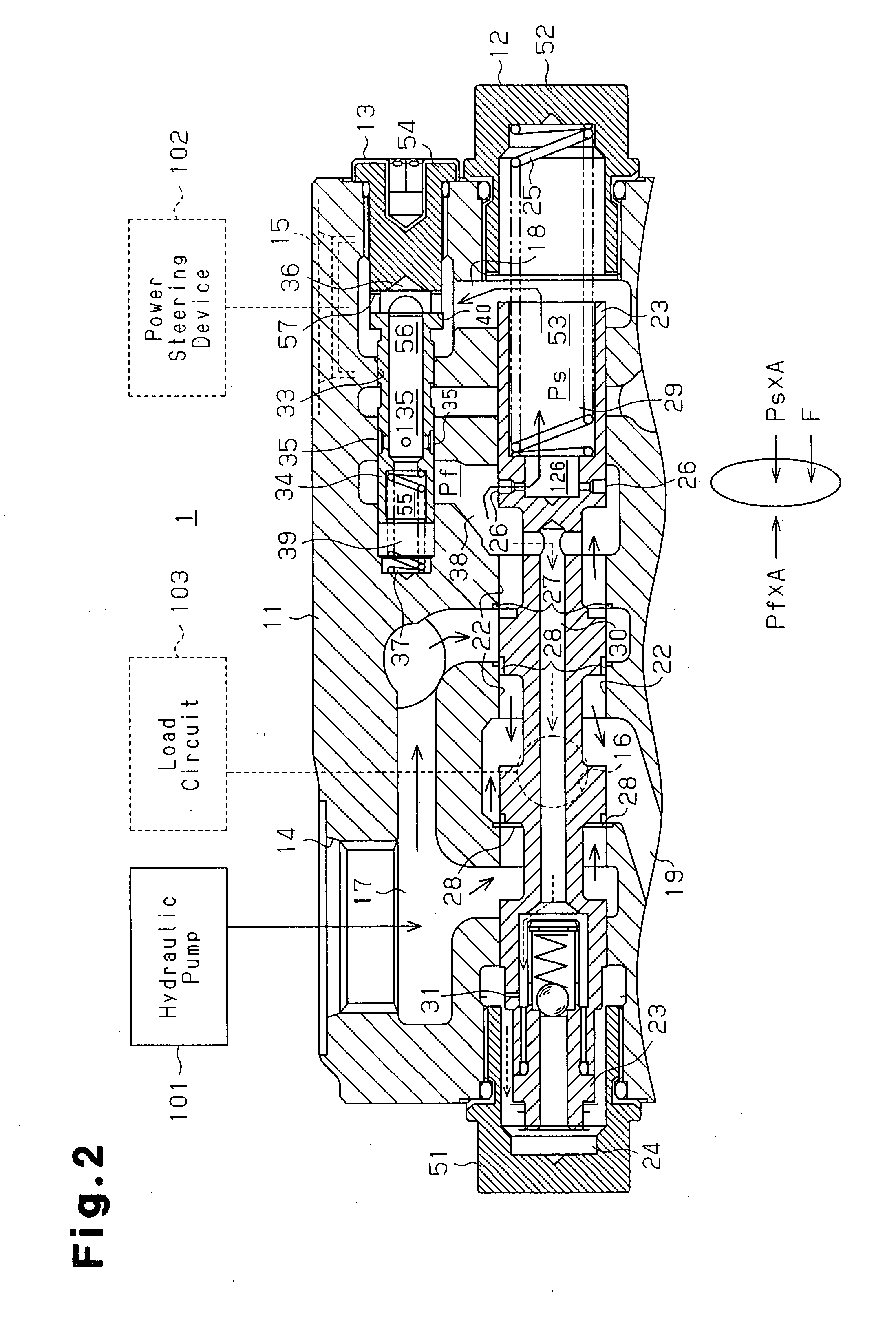
[0017]FIG. 1 is a cross-sectional view of a flow rate switching type flow divider 1. The flow rate switching type flow divider 1 may be applied to, for example, a forklift so as to distribute hydraulic oil, which functions as an operating fluid, supplied from a hydraulic pump 101 to a hydraulic power steering device 102, which functions as a priority flow circuit, and to a load circuit 103, which functions as a surplus flow circuit. The load circuit 103 functions as an actuator circuit for controlling the operation of various types of hydraulic actuators used for handling loads. The flow rate switching type flow divider 1 is not necessari...


PUM


Abstract

A flow rate switching type flow divider for distributing fluid from a pump to a priority flow circuit and a surplus flow circuit. A flow divider valve arranged along a first line includes a first restriction to restrict flow rate of the fluid from the supply flow path to the priority flow path. A switch valve is arranged along a second line that differs from the first line so as to communicate with the supply flow path through the flow divider valve at a location upstream from the first restriction. The switch valve switches an opening amount of a connection flow path that bypasses the first restriction and extends from the supply flow path to the priority flow path. The switch valve includes a second restriction arranged in the switch valve for restricting flow rate of fluid flowing through the connection flow path.

Description

TECHNICAL FIELD[0001]The present invention relates to a flow rate switching type flow divider for supplying fluid from a pump at a predetermined flow rate to a priority flow circuit, while also supplying fluid through a tributary flow to a surplus flow circuit.BACKGROUND ART[0002]In the prior art, known flow rate control valves and load sensing flow priority valves supply hydraulic oil, which functions as an operating fluid, from a pump to a priority flow circuit at a predetermined flow rate, and supply the remaining oil to a surplus flow circuit. Japanese Laid-Open Patent Publication No. 7-323855 describes a flow priority valve that has a body including a supply port, a control flow port, and a surplus flow port. A main spool is accommodated in the body. The main spool has a first end, facing toward a pilot chamber, and an opposite second end. A casing member is fitted to the body so as to face the second end of the main spool. An auxiliary spool is movably accommodated in the casi...

Claims


Application Information

Patent Timeline
Patent Type & Authority Applications(United States)
IPC IPC(8): F16K31/12
CPCF15B13/022Y10T137/2605
Inventor MATSUZAKI, TAKEHARUNAKAJIMA, SHIGETO
Owner TOYOTA IND CORP
Why Eureka
Try Eureka