
Sliding Nozzle Device and Pouring Device

a technology of sliding nozzle and pouring device, which is applied in the direction of casting apparatus, melt-holding vessel, manufacturing tools, etc., can solve the problems of lack of practical use and lack of reliability of the sliding mechanism of the sliding apparatus described in patent document 2 , to achieve the effect of convenient selective setting and execution

Inactive Publication Date: 2008-11-06
NIPPON ROTARY NOZZLE +3
View PDF1 Cites 5 Cited by
  • Summary
  • Abstract
  • Description
  • Claims
  • Application Information

AI Technical Summary

Benefits of technology

[0008]This invention is made by paying attention to a problem existing in the prior art mentioned above. An objective of this invention is to provide a sliding nozzle apparatus and a pouring apparatus which can reliably apply a pressing force to an opening and closing metal frame and cancel the pressure application on the basis of a simple structure.
[0010]In this case, the spring is deformed against the urging force on the basis of the operation of the cam surface in accordance with the movement of the actuating member, and the pressurizing force against the opening and closing metal frame is strengthened. Accordingly, the toggle mechanism is not necessary, the structure is simple, and it is possible to reliably apply the pressurizing force to the opening and closing metal frame, and cancel the force application.
[0012]In this case, the holding member is moved from the position holding the opening and closing metal frame to the position separated therefrom, by rotating the rotating member in the state in which the pressurizing force applied to the opening and closing metal frame is weakened, whereby it is possible to easily disconnect the opening and closing metal frame from the fixed metal frame.
[0014]In this case, it is possible to reliably hold the opening and closing metal frame to the closed position via the actuating member, by utilizing the reaction force in accordance with the elastic deformation of the spring.
[0016]In this case, since the actuating member is constituted by two parts comprising the moving member and the cam member, the structure of the actuating member is simple, and it is possible to reliably regulate the pressurizing force applied to the opening and closing metal frame via the cam member on the basis of the movement of the moving member constituting the actuating member.
[0018]In this case, it is possible to easily selectively set and execute a control of regulating the pressurizing force applied to the opening and closing metal frame and a control of opening and closing the passage between the nozzle holes, by switching the cam member to the state of being moved integrally with the movable plate and the state of being fixed to the opening and closing metal frame.

Problems solved by technology

However, the sliding apparatus described in Patent Document 2 is structured such that in addition that the switching mechanism is arranged in a narrow space between the fixed metal frame and the opening and closing metal frame, the toggle mechanism having a complicated structure including the spring is provided inside of the switching mechanism, and the member constituting the toggle mechanism operates a complicated motion.
Accordingly, the switching mechanism of the sliding apparatus described in Patent Document 2 lacks a reliability of the motion, and has not been put into practical use.

Method used


Image

  • Sliding Nozzle Device and Pouring Device
  • Sliding Nozzle Device and Pouring Device
  • Sliding Nozzle Device and Pouring Device

Examples


embodiment

(Operation of Embodiment)

[0056]Next, a description will be given of an operation of the sliding nozzle apparatus 12 structured as mentioned above.

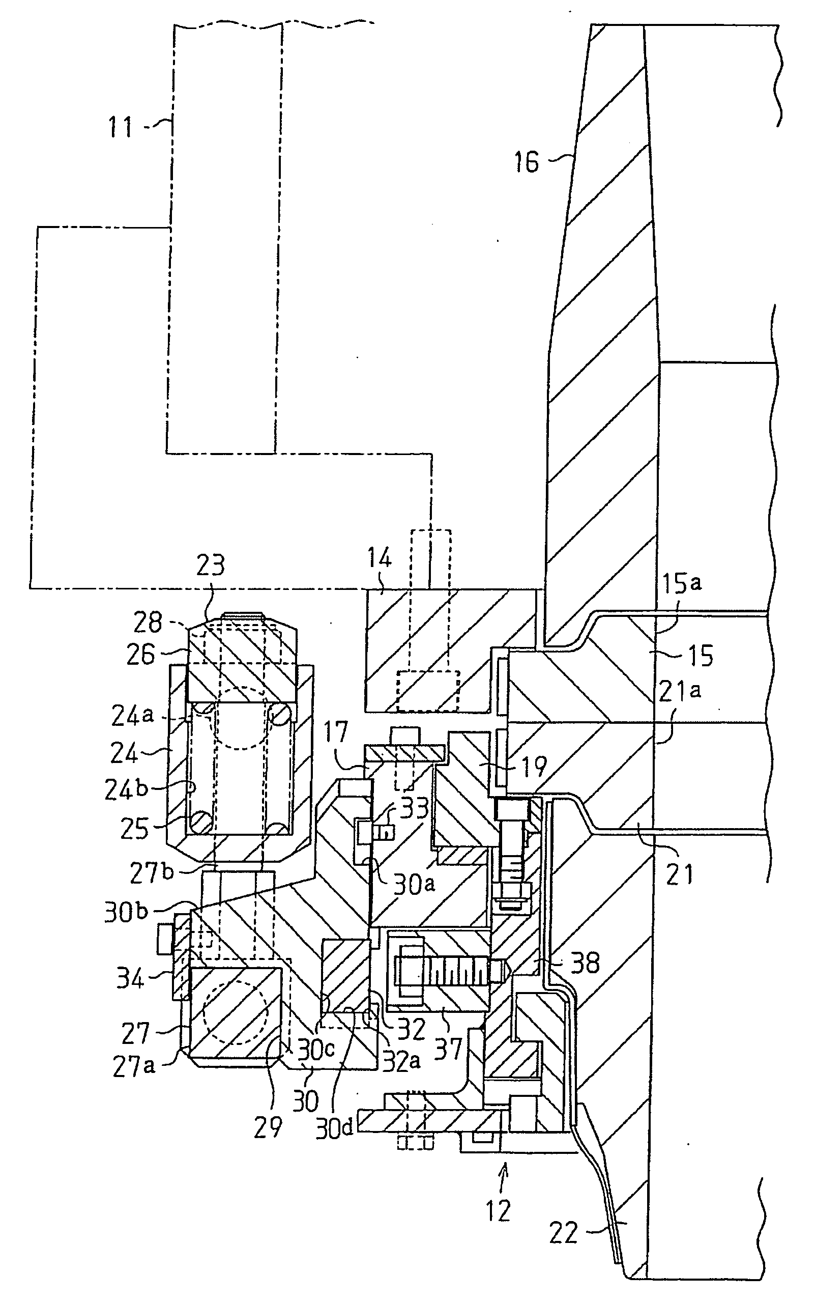
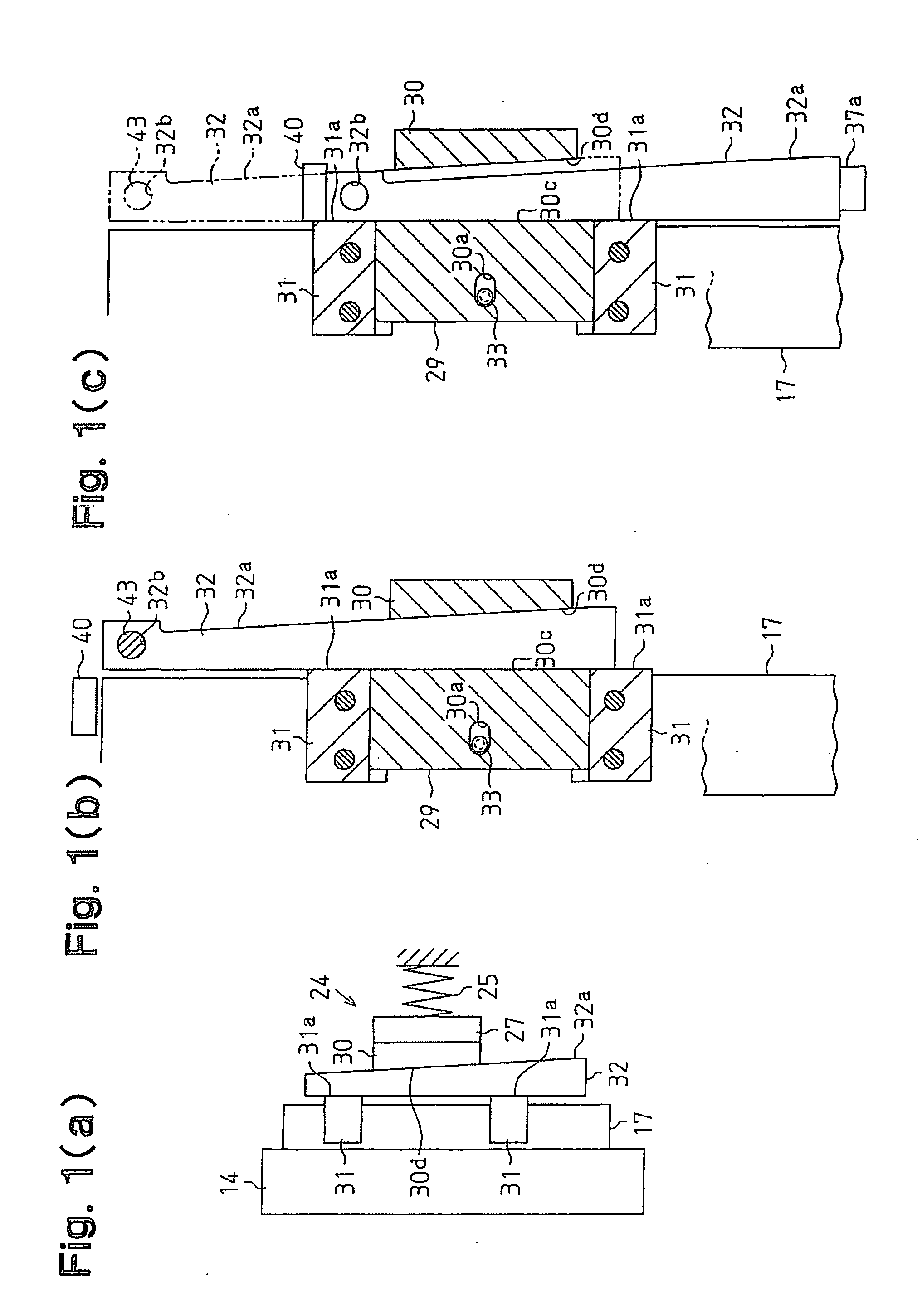
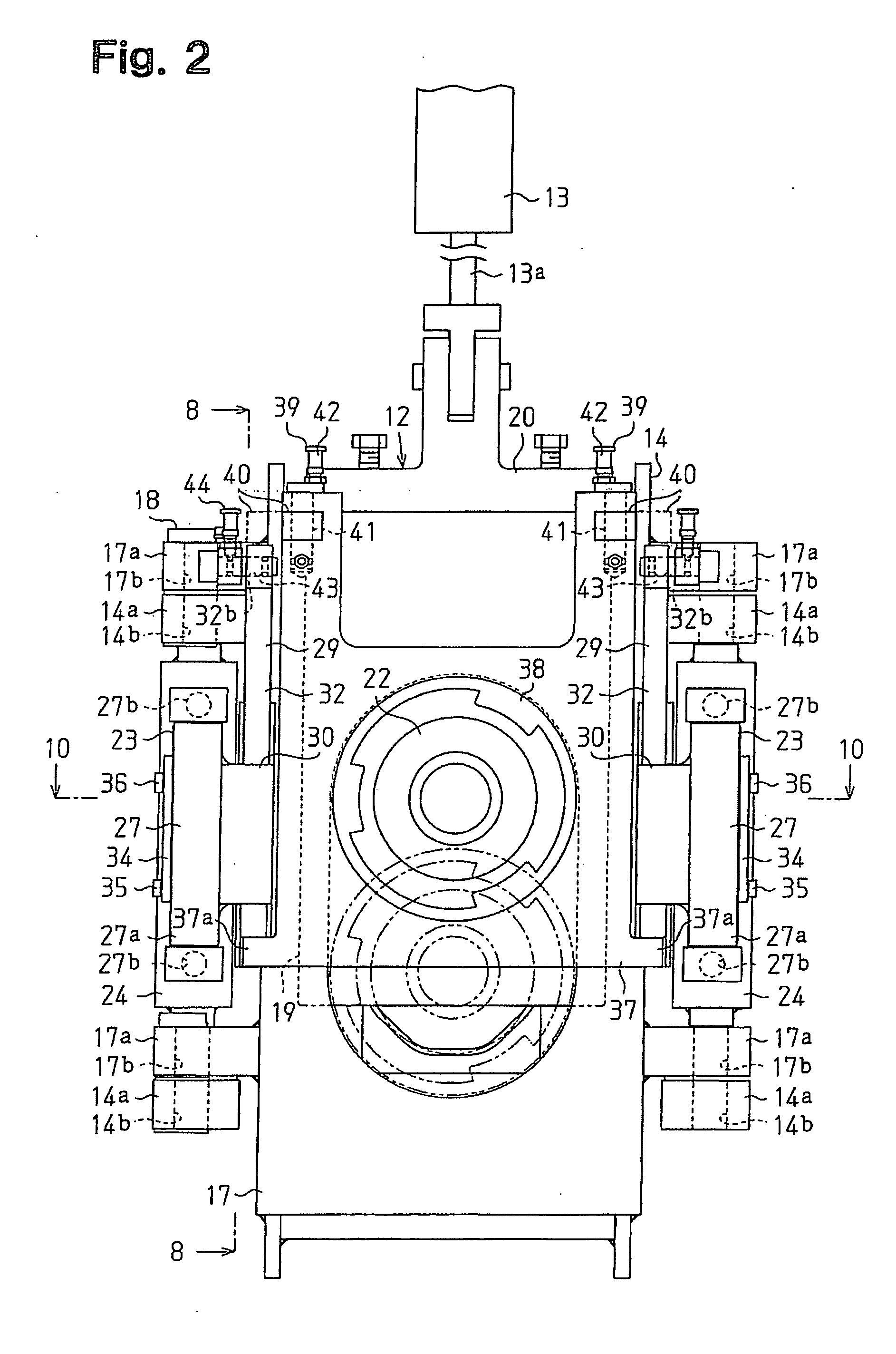
[0057]At a time of a normal use of the sliding nozzle apparatus 12, the opening and closing metal frame 17 is arranged at the closed position with respect to the fixed metal frame 14, and the holding members 27 of the pressurizing mechanisms 23 are rotated and arranged at the held position with respect to the opening and closing metal frame 17, as shown in FIGS. 6 and 7. In this state, as shown by a two-dot chain line in FIG. 4, the sliding metal frame 19 is moved to a lower side in FIG. 4, and the passage between the nozzle holes 15a and 21a of both the plates 15 and 21 is closed. Further, as shown by a solid line in FIG. 8, the cam members 32 are moved to one end (an upper end in FIG. 8) in a moving range, and the fixing pins 43 are engaged with the engagement holes 32b, thereby being fixed to the opening and closing metal frame 17.

[0058...

modified examples

[0069]In this case, the embodiment can be embodied by being changed as follows.

[0070]The structure may be made such that the moving members 30 are omitted, the cam members 32 are directly brought into contact with the holding members 27 of the pressurizing mechanisms 23, and the holding members 27 are moved against the spring force of the coil springs 25 on the basis of the cam operation.

[0071]The structure may be made such that the sliding metal frame 19 and the interlocking frame 37 are integrated, and the sliding metal frame 19 is provided with a means such as the engagement projection 37a or the like for supporting the cam member 32.

[0072]The structure may be made such that the cam surfaces 30d and 32a are provided in any one of the moving member 30 and the cam member 32.


PUM

PropertyMeasurementUnit
pressureaaaaaaaaaa
pressurizing forceaaaaaaaaaa
elasticityaaaaaaaaaa

Abstract

A fixed plate (15) is provided in a fixed metal frame (14). An opening and closing metal frame (17) having a movable plate (21) is attached to the fixed metal frame (14) so as to be openable and closable. The fixed metal frame (14) is provided with a pressurizing mechanism (23) applying a pressure in a closing direction generated by a spring (25) to the opening and closing metal frame (17) in a closed state. An actuating member (29) is movably provided at a position facing the pressurizing mechanism (23). Cam surfaces (30d, 32a) are provided between the actuating member (29) and the pressurizing mechanism (23). The spring (25) is deformed against an urging force thereof on the basis of operations of the cam surfaces (30d, 32a) in accordance with a movement of the actuating member (29), and the pressure applied to the opening and closing metal frame (17) is strengthened.

Description

TECHNICAL FIELD[0001]This invention relates to a sliding nozzle apparatus attached to a molten metal container such as a ladle or the like, for example, used in a continuous casting line, and provided for controlling a pouring amount at a time of pouring a molten metal to a casting mold from the molten metal container, and a pouring apparatus provided with the sliding nozzle apparatus.BACKGROUND ART[0002]This kind of sliding nozzle apparatus is provided with a fixed plate fixed to a molten metal container such as a ladle or the like, and a movable plate facing the fixed plate. A fixed nozzle is provided on the fixed plate, and a movable nozzle is provided on the movable plate, respectively. Further, when the nozzle or the like is replaced or maintained, the movable plate is rotated, and the movable plate and the movable nozzle are separated from the fixed plate and the fixed nozzle. Further, at a time of pouring, the movable plate and the movable nozzle are slid in a state of being ...

Claims


Application Information

Patent Timeline
Patent Type & Authority Applications(United States)
IPC IPC(8): B22D41/50B22D11/10B22D41/34B22D41/40
CPCB22D41/34B22D41/40B22D41/24
Inventor KONDO, TSUNEOTAKASUGI, HIDETOUMEMURA, MITSUOKAWAI, YOSHINOBUYOTABUN, TOMOHIROIKEDA, HISAMORIINUBUSHI, HISAO
Owner NIPPON ROTARY NOZZLE
Learn More