Jet Engine Exhaust Nozzle Flow Effector

a jet engine and effector technology, applied in the direction of machines/engines, sustainable transportation, transportation and packaging, etc., can solve the problems of inability to perform detailed parametric investigations using static chevrons, slowed their incorporation into production engines, and many lessons about parametric design space. to achieve the effect of reducing the noise of the jet engin

Inactive Publication Date: 2008-11-06
NASA
View PDF12 Cites 17 Cited by
  • Summary
  • Abstract
  • Description
  • Claims
  • Application Information

AI Technical Summary

Benefits of technology

[0007]Accordingly, it is an object of the present invention to provide a flow effect

Problems solved by technology

Jet exhaust-nozzle chevron systems are a proven noise reduction technology, but much is yet to be learned about their parametric design space.
Furthermore, a tradeoff between noise reduction at takeoff and thrust loss at cruise has slowed their incorporation into production engines.
However, detailed parametric investigations using static chevrons are not feasible because of the high cost of fabr

Method used


Image

  • Jet Engine Exhaust Nozzle Flow Effector
  • Jet Engine Exhaust Nozzle Flow Effector
  • Jet Engine Exhaust Nozzle Flow Effector

Examples


Embodiment Construction

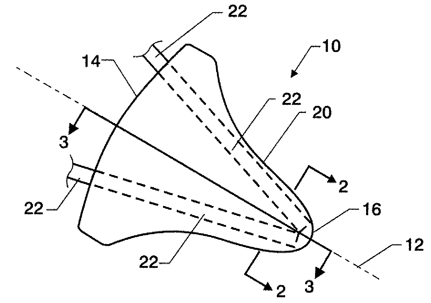
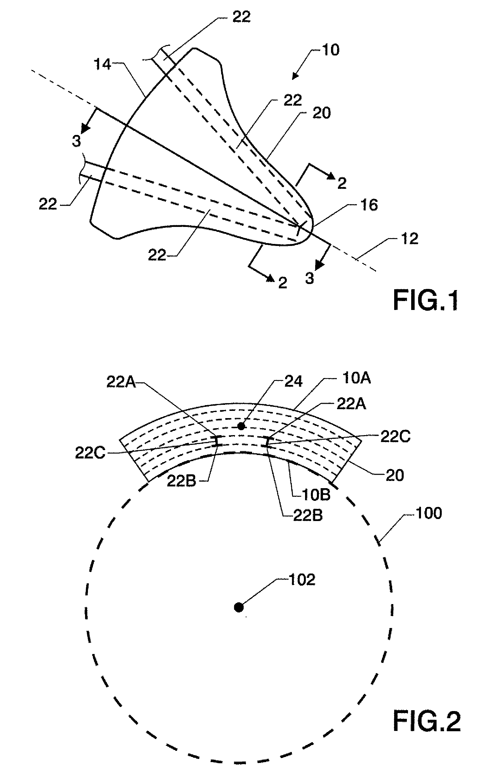
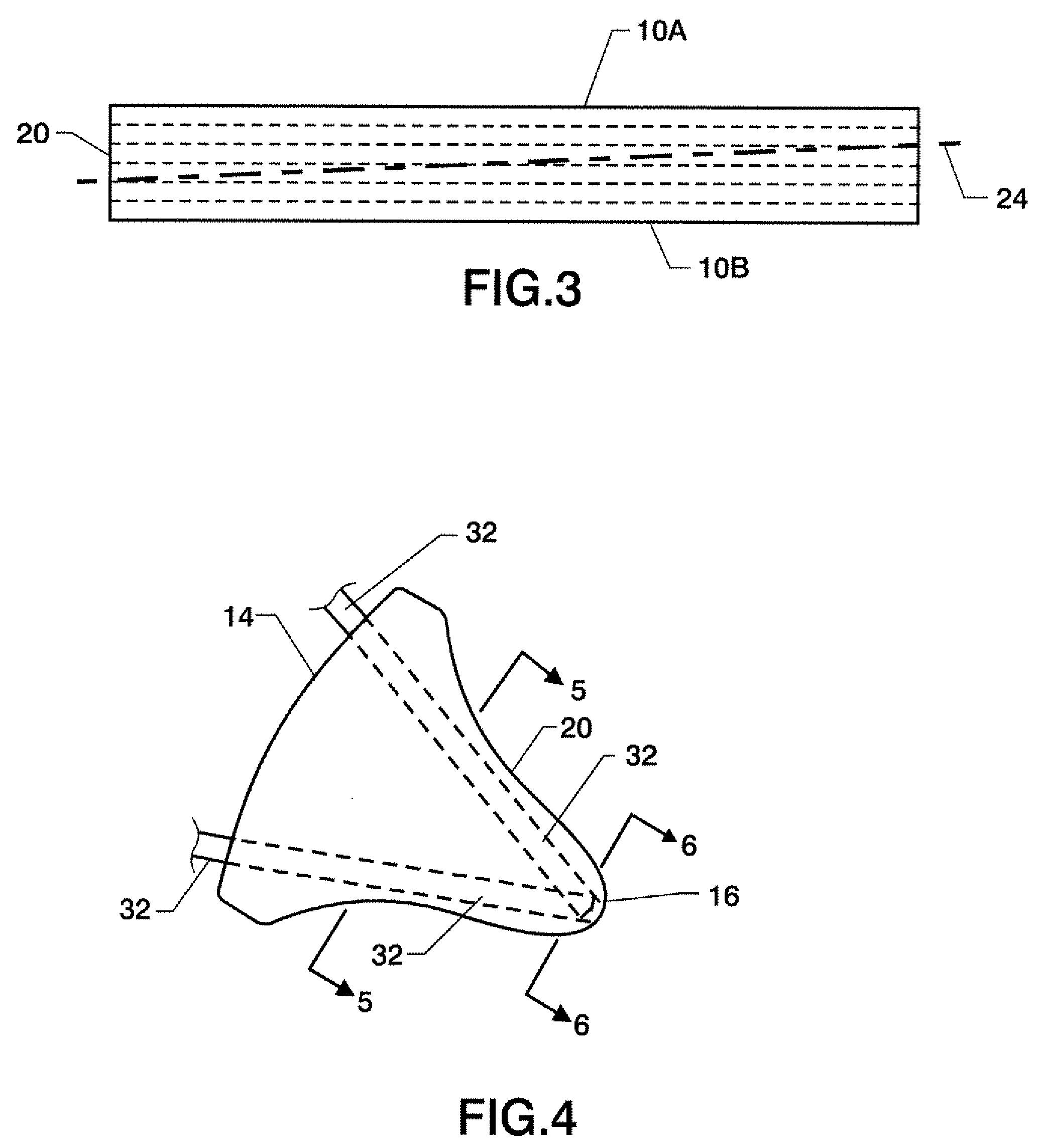
[0025]Referring now to the drawings, simultaneous reference will be made to FIGS. 1-3 where a first embodiment of a flow effector for use in controlling jet engine noise is illustrated and is referenced generally by number 10. Flow effector 10 is generally a chevron-shaped flow effector that is symmetrical about its centerline referred by dashed line 12. In its chevron shape, flow effector 10 has a root 14 and a tip 16. When used in conjunction with a jet engine, flow effector 10 is mounted to the jet engine's nozzle. More specifically and as would be understood in the art, root 14 is attached to a region of the jet engine nozzle such that tip 16 is positioned aft of the nozzle's exit (illustrated in FIG. 2 by dashed line 100). In the illustrated example, the jet engine nozzle exit 100 is assumed to be circular so that flow effector 10 has a cylindrical radius of curvature that is geometrically matched to a portion of nozzle exit 100. However, as will be explained further below, the...


PUM


Abstract

A jet engine exhaust nozzle flow effector is a chevron formed with a radius of curvature with surfaces of the flow effector being defined and opposing one another. At least one shape memory alloy (SMA) member is embedded in the chevron closer to one of the chevron's opposing surfaces and substantially spanning from at least a portion of the chevron's root to the chevron's tip.

Description

ORIGIN OF THE INVENTION[0001]The invention was made by employees of the United States Government and may be manufactured and used by or for the Government of the United States of America for governmental purposes without the payment of any royalties thereon or therefor. Pursuant to 35 U.S.C. §119, the benefit of priority from provisional applications 60 / 805,262 with a filing date of Jun. 20, 2006, and 60 / 895,202 with a filing date of Mar. 16, 2007, is claimed for this non-provisional application.BACKGROUND OF THE INVENTION[0002]1. Field of the Invention[0003]This invention relates to flow effector design. More specifically, the invention is an active flow effector that can be coupled to a jet engine exhaust nozzle to affect the flow exiting therefrom.[0004]2. Description of the Related Art[0005]Reduction of let engine noise in the vicinity of airports continues to be of paramount importance. Jet exhaust-nozzle chevron systems are a proven noise reduction technology, but much is yet ...

Claims


Application Information

Patent Timeline
IPC IPC(8): B64C13/00
CPCF02K1/386F02K1/48Y02T50/671F05D2300/505Y02T50/60
Inventor CAGLE, CHRISTOPHER M.CABELL, RANDOLPH H.TURNER, TRAVIS L.CANO, ROBERTO J.SILCOX, RICHARD J.BUEHRLE, RALPH D.HILTON, GEORGE C.
Owner NASA
Why Eureka
Try Eureka