
Microjet noise suppression system for jet engines

Inactive Publication Date: 2012-07-24
FLORIDA STATE UNIV RES FOUND INC
View PDF11 Cites 2 Cited by
  • Summary
  • Abstract
  • Description
  • Claims
  • Application Information

AI Technical Summary

Benefits of technology

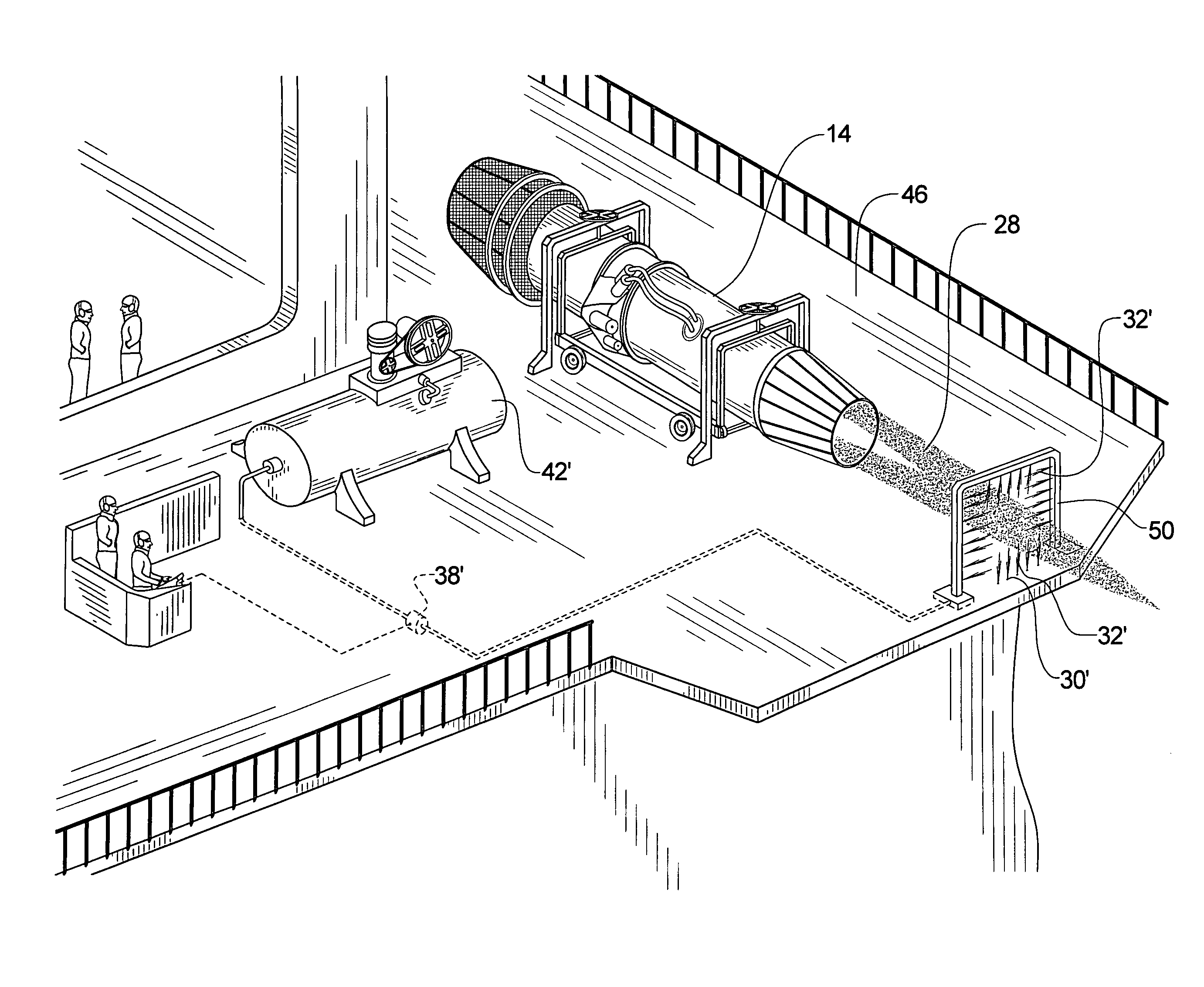
[0011]The microjet noise suppression system for jet engines of the present invention helps reduce jet engine noise by attacking the various components of the far-field noise of the jet.
[0012]High pressure microjets are introduced for the suppression of the dominant large scale mixing noise source of a jet. These microjets introduce either an output stream, which stream may be steady or pulsed or a combination thereof, which stream is either gaseous or aqueous. The microjet stream is injected into the primary jet stream at and beyond the nozzle exit in order to manipulate the dominant source region, which region typically extends from about 5 to about 20 nozzle diameters from the nozzle exit. The interaction of the microjet jet stream or pulse interacts with the jet shear layer and reduces the turbulence levels in the noise producing region of the jet. The microjet jet stream or pulse influences the mean velocity profiles such that the peak normalized vorticity in the shear layer is significantly reduced which induces a stabilizing effect.

Problems solved by technology

Although jet engines have become quieter over the years, noise produced by jet engines continues to be a problem for many especially at and near airports where the jet plane is on or near the ground and where jet pressure is high either to achieve V-2 takeoff speed or for reverse thrust to brake an airplane.
As many airports are located in urban and suburban areas with development constantly encroaching, jet engine noise is a sizable problem.
This maximum thrust results in a very high noise output.
This source of noise is associated with the unsteady flow that is on a scale that is comparable with the local shear layer width.

Method used


Image

  • Microjet noise suppression system for jet engines
  • Microjet noise suppression system for jet engines
  • Microjet noise suppression system for jet engines

Examples


Embodiment Construction

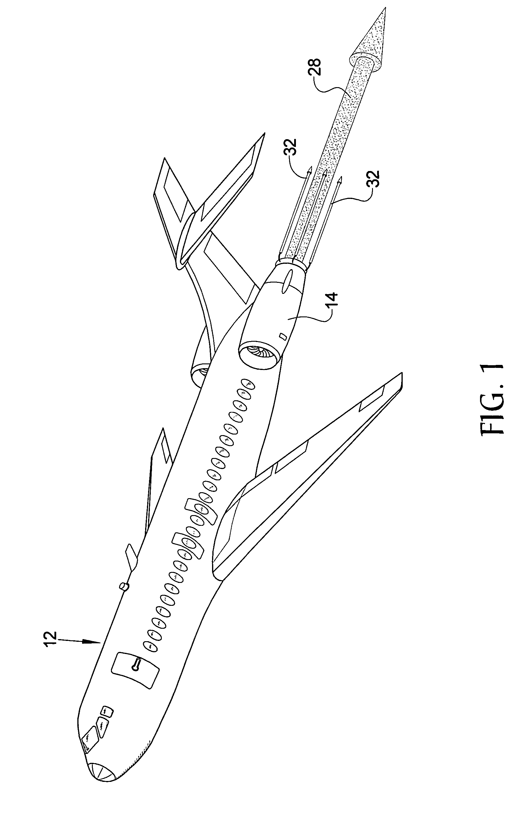
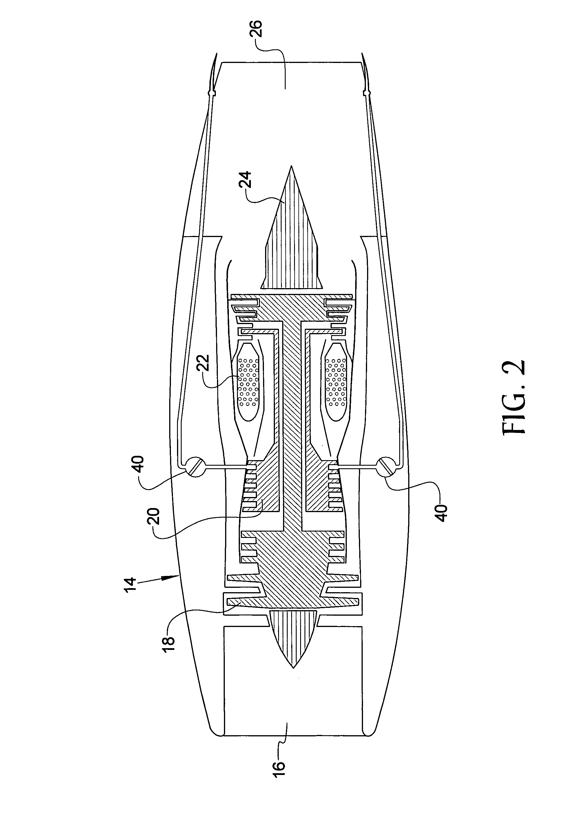
[0021]Referring now to the drawings, it is seen that the microjet noise suppression system for jets of the present invention, generally denoted by reference numeral 10, is installed on a typical jet aircraft 12, which can be a typical commercial aircraft (Boeing 717, 737, 747, 757, Airbus A300, etc.), a military jet aircraft, either transport (C141, etc.), or fighter (F14, FA18, etc.), or a general aviation jet aircraft (Learjet, Gulfstream etc.), wherein one or more jets 14 provide forward thrust for the aircraft 12. As seen in FIG. 2, a typical jet 14 has several major components including an inlet 16 for drawing working air into the jet 14, a low pressure compressor 18, a high pressure compressor 20, a burner can 22, an exhaust cone 24, and an exhaust 26 from where jet exhaust 28 issues. It is understood that other jet configurations are possible and that the above is illustrative of a general jet architecture.

[0022]At least one microjet 30 is located downstream of most of the ma...


PUM


Abstract

A jet engine noise suppression system uses a plurality of microjets that are located on a frame downstream of the exhaust port of a jet engine. Each microjet issues a microjet flow, either liquid or gas, directed at the main jet flow issued by the engine. The mass of the combined microjet flow is substantially smaller than the mass of the jet engine flow. The angle of at which each microjet issues its flow may be variable. The microjets may be located on a pop-up head of a blast deflector or on a upstanding rack.

Description

[0001]This application claims the benefit of provisional patent application No. 60 / 933,515 filed on Jun. 7, 2007, which provisional application is incorporated herein by reference, and is a Continuation-in-Part of utility patent application Ser. No. 10 / 864,281, filed on Jun. 9, 2004 now abandoned, which claims the benefit of provisional patent application 60 / 477,065 filed on Jun. 9, 2003, all incorporated herein by reference.BACKGROUND OF THE INVENTION[0002]1. Field of the Invention[0003]The present invention relates to a noise suppression system for jet engines whereby a plurality of microjets pulse a microjet output at the main exhaust stream emanating from the microjet, the microjets being located either directly on the aircraft or externally of the aircraft.[0004]2. Background of the Prior Art[0005]Although jet engines have become quieter over the years, noise produced by jet engines continues to be a problem for many especially at and near airports where the jet plane is on or ...

Claims


Application Information

Patent Timeline
IPC IPC(8): F02K1/00
CPCF02K1/34
Inventor KROTHAPALLI, ANJANEYULUGRESKA, BRENTON
Owner FLORIDA STATE UNIV RES FOUND INC
Learn More